Fisher Model and Pattern
[ page 1 ]
F7U-3M Cutlass in 1/32 scale: building the Fisher Model and Pattern kit
The Chance Vought F7U-3M Cutlass kit #3209 is of the small company Fisher Model and Pattern that made special larger scale models for the enthusiast. This kit was purchased in 2017 and though not cheap offers a special large 1/32 model of this unique fighter, the Cutlass.
I have made a 1/32 Fisher kit of the F9F Panther and have a few kits still to be made.
Please consider this modelling report as a Big Thank You to Paul Fisher and family who gave us larger scale modellers excellent and unique kits to build for the modeller enthusiast.
About the Vought F7U Cutlass
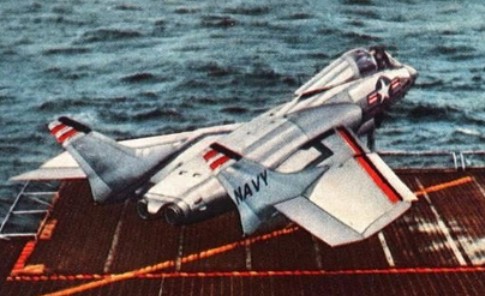
The Vought F7U Cutlass was a United States Navy carrier-based jet fighter and fighter-bomber of the early Cold War era. Design V-366 was a highly unusual, semi-tailless design and pretty large. Pitch and roll control was provided by elevons, though Vought called these surfaces "ailevators" at the time. Slats were fitted to the entire span of the leading edge. The first XF7U-1 flew in September 1948.
Several versions were developed. The F7U-1 was very close to the 6 prototypes and 14 were built. The US Navy Flight Demonstration Squadron, the Blue Angels, flew two F7U-1 Cutlasses as a side demonstration during their 1953 show season but this was not a success. The next version was to be the F7U-2 but that was cancelled.
What followed was the F7U-3M that would be the definitive production version. It was significantly different from the F7U-1 with another nose profile and larger airframe with many more access doors for maintenance. The single nose wheel was soon replaced by a dual pair but still the nose gear gave problems. It also got 4 20mm guns in the upper intake lips. The later versions got other ejection seat and different wind shield. Also, a missile firing version was developed, the F7U-3M could fire the first generation Sparrow 1 missile with 4 pylons to be fitted. Some 50 earlier F7U-3 aircraft were modified to -3M standard.
Apart from the fighter, it was envisaged to use the Cutlass for photo reconnaissance. Some 6 reconnaissance F7U-3P aircraft were made with a 25" longer nose fitted with cameras. Guns were removed. First flight was July 1954. But in the end this version was only used for trials.
The Cutlass had a very long nose landing gear strut required for high angle of attack carrier landings and that gave many problems. Also, the aircraft was underpowered with its Westinghouse J46 jets and its afterburner reduced its range a lot. The type had also numerous technical issues like flame outs and handling problems. It was not liked by pilots as it had only little margin of error, killing many pilots in fatal accidents.
A total of about 28 F7U-1 and 274 F7U-3 aircraft were manufactured equipping a dozen U.S. Navy squadrons including later on some 50 converted F7U-3 to -3M standard. ("M" for missile capability). The Cutlass aircraft was mostly operated from shore, only a few deployments were actually for a Tour made from US aircraft carriers and even than the type operated abroad from nearby shore bases. Eventually, the Cutlass served only a short period with the U.S. Navy and went out of service in 1957.
Also see my Cutlass scrap info page with some real aircraft info....
(note: this a copy of my own text also published at the IPMS.NL Cutlass walk around . This walk around is recommended to study also for details of the real aircraft; see also references).
---
page 1
page 2
page 3
page 4
page 5
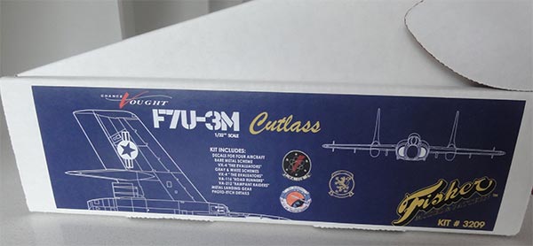
All parts of the Chance Vought F7U-3M Cutlass kit #3209 come in a strong and heavy carton box. The instructions are black and white pages with photos and text, the old style found in old kits.
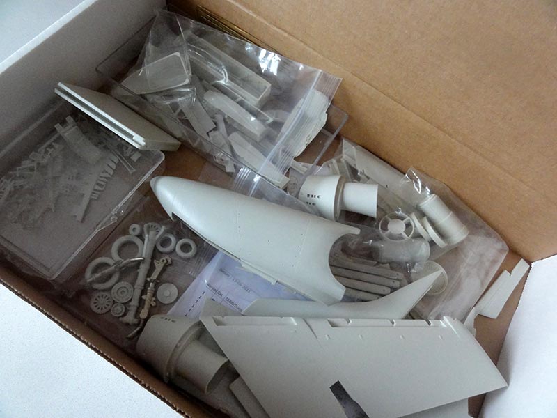
All components look crisp and need a lot less work as usually found in resin kits. The moulding technique as used is superb and parts are crisp with just a few gaps and flash, these are easily coped with. This is a great kit.
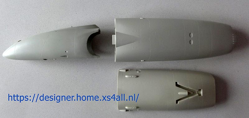
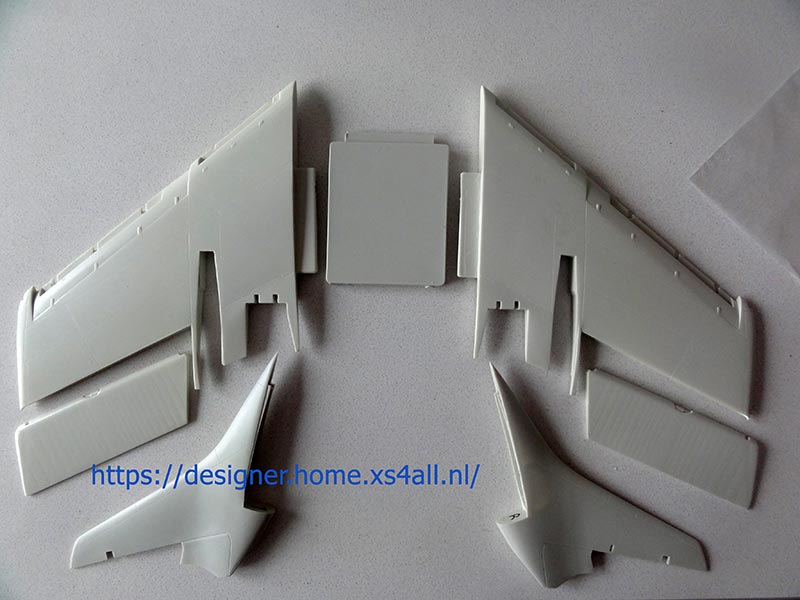
There are not that many big components and the bigger parts like main fuselage and nose hardly need any work, they have been provided as almost ready to use parts.
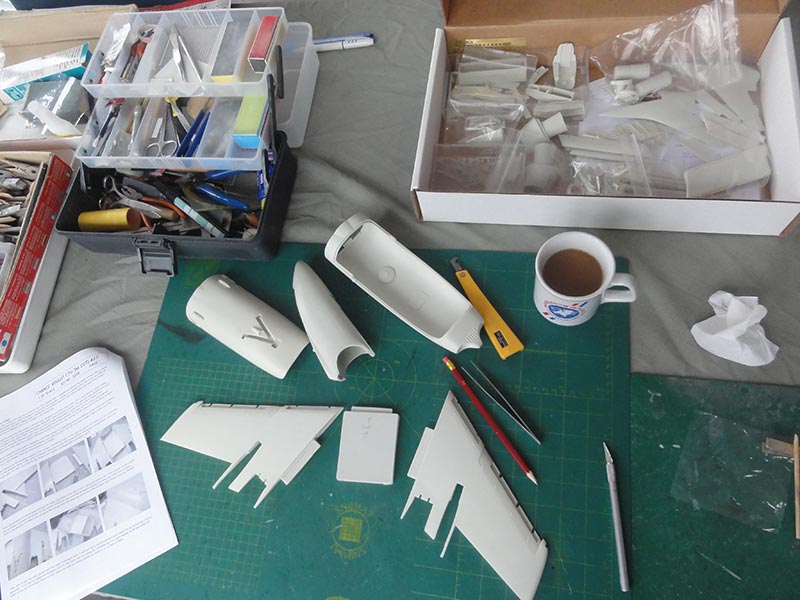
The impressive bigger components are seen here...
First thing is to do is to wash the components in water with some soap to remove any release agent. Make sure not to loose any parts so use a tub.
Handling resin parts may be harmful, so read my resin handling tips here...

Next, some parts were separated from the moulding blocks with a fine saw and X-acto blade.
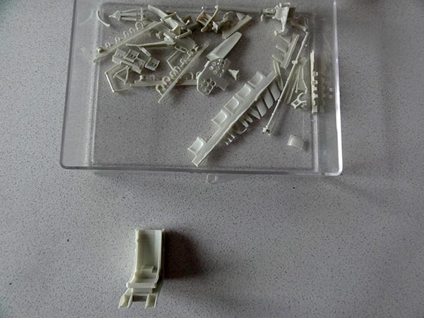
Note: there are a lot of smaller parts and in order not to mix them up, I not yet separated these tiny bits. The parts were kept in separate containers and bags.
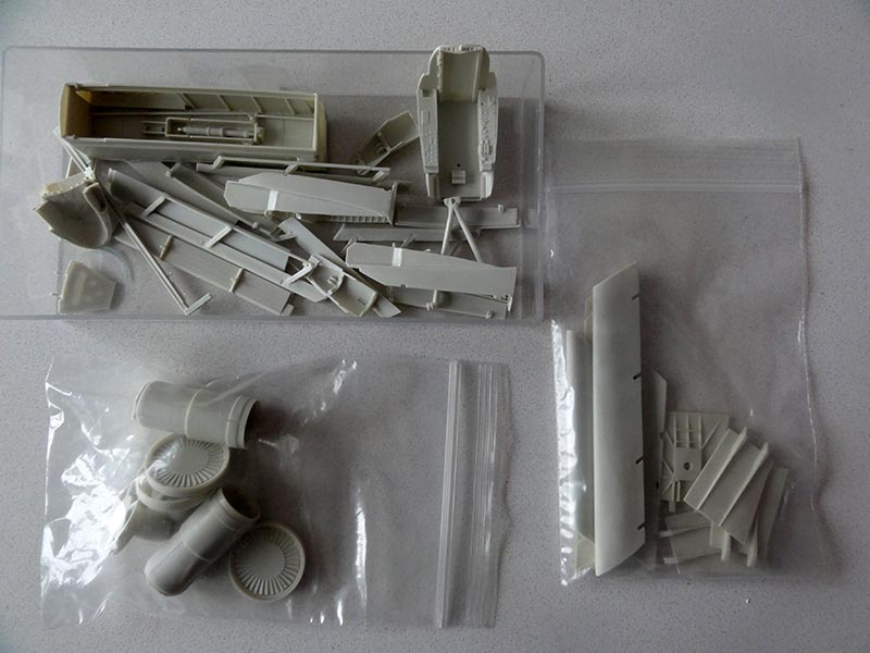
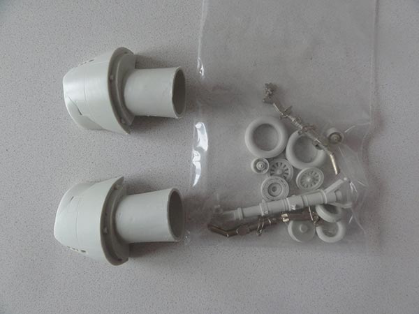
The pair of wing main landing gear legs are in casted metal by G-Factor in the kit. This is well as the weight of this kit is a lot.
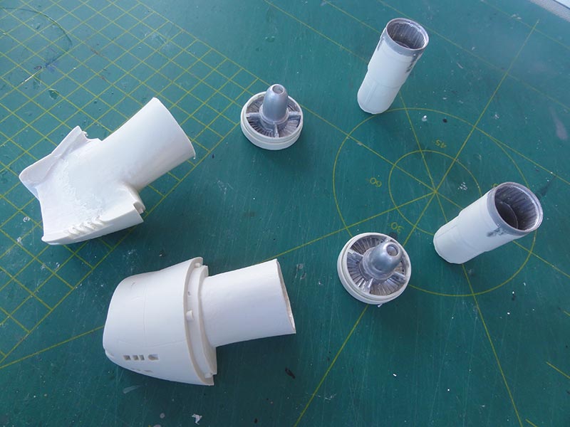
The intakes have a nice intake funnel extension.
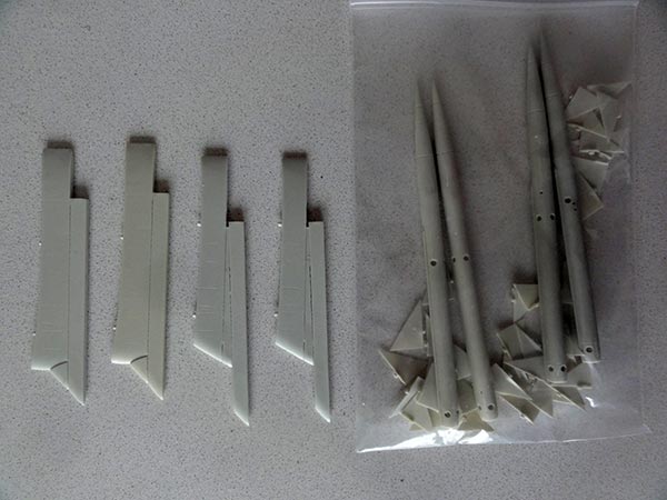
Four pylons and early Sparrow Type 1 missiles are provided as used on the later F7U-3M ("M" for missile). Very nice and these missiles can be finished in interesting colours.
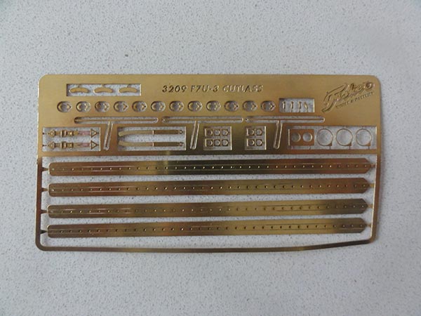
The kit also has a metal fret amongst which are the trailing edge stringers seen on the Cutlass "flapperons". You get a few spare ones as well.
-----------
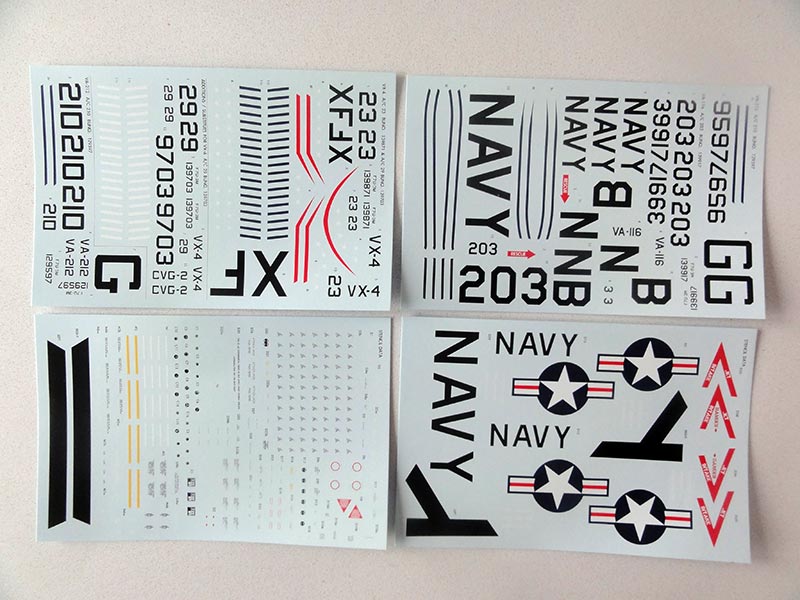
The decals printed by Microscale look great and have schemes for four US Navy F7U-3 :
[1] VA-116 Road Runners in a gull gray - white scheme Bur.no 139917
[2] VA-212 Rampant Raiders in a gull gray - white scheme Bur.no 129597
[3] VX-4 The Evaluators in a gull gray - white scheme Bur.no 139703
[4] VX-4 The Evaluators in a natural metal and silver scheme Bur.no 139871.
For scheme [4] a very nice drawing of the different metallic hues seen on aircraft (it is from the official manual and also shown on the scrap page....). This VX-4 natural metal F7U-3M aircraft has also blue tail tips and blue wing tips. I saw that red bordering stripes on the decal sheet are provided adjacent to the blue areas for the tail tips and canopy border but not for the blue wing tips.
Decals are provided for stencilling and the early Sparrow 1 missiles and stencilling for the airframe.
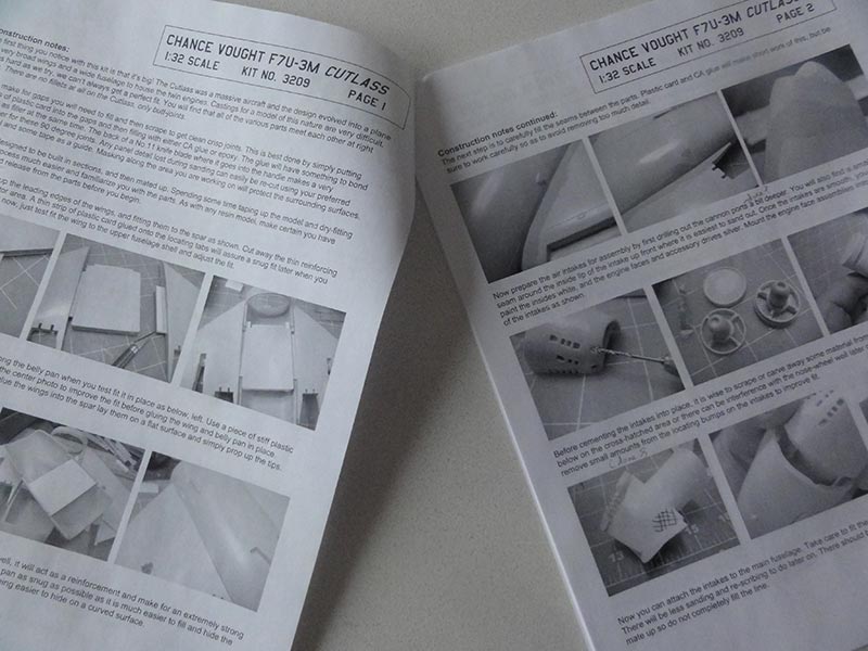
For this built I followed the steps as suggested in the instructions coming with the kit. Each STEP PAGE will be indicated while building this kit.

As noted, first thing is to do is to wash the components in water with some soap to remove any release agent. Make sure not to loose any parts so use a tub.
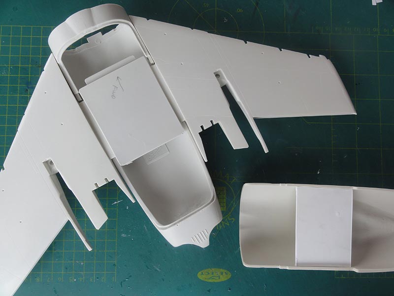
The first step is preparing the main fuselage and wing halves, which are impressive big clean components. Just a bit of sanding the wing leading edges is needed.
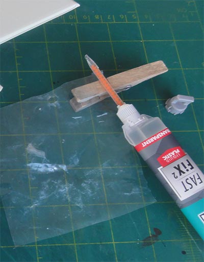
The assembly of this kit needs two component filler glue for stronger joints and super glue for the smaller parts. I used Bison Fast Fix2 glue and Zap Slo-zap.

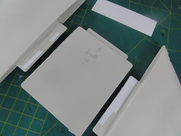
There is a spar block provided to get the wing halves fixed horizontally with the central fuselage. I needed a bit of thin plastic card in some areas set onto the lugs to get a tight fit. Mark the forward direction to avoid wrong assembly. The instructions are very clear.
The wing halves are to be fitted horizontal without anhedral/dihedral.
Inside the fuselage it is also suggested to make a spacer to avoid a tiny ridge on the sides when assembled. I used a piece of thick card.
Inside the rear exhaust holes I scraped a bit material off to ensure that the excellent deep exhaust pipes will fit later on.
Just to make sure and have extra strength, I also made a thick metal spar running through quite some length in the wing halves and fuselage. Holes were drilled and the spar set. Make sure to keep the wing horizontal. (Sorry: I forgot to make photos).
STEPS PAGE 2
The wing was fitted and the lower fuselage shell. At this point the small junction gaps between wing and fuselage were filled with Alabastine car filler. Joints should have 90 degree angle.
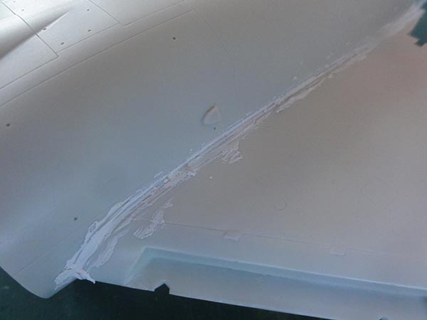

 When dried, all was sanded. (the leading edge slat inserts will follow later).
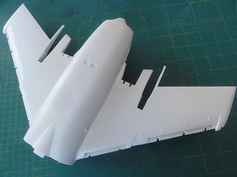
 The intakes look great, I drilled open a bit the gun ports. The engine fans were painted metal as well as the insides of the exhaust pipes.
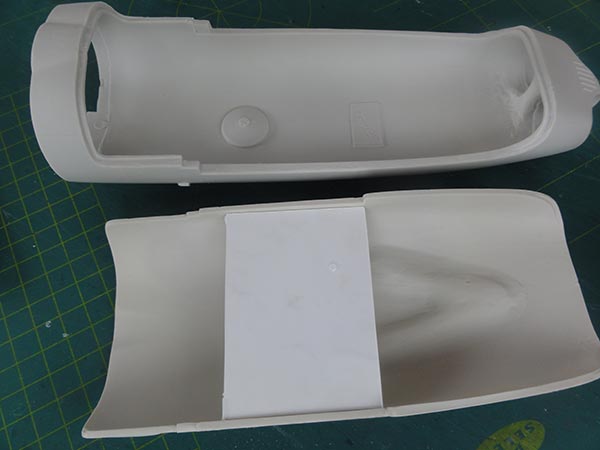
Now the intakes were dry fitted to the central fuselage. A bit scraping is needed on the insides to get a good fit, this is shown in the instructions. The remaining gap is very small though and so no issues here. Only a bit filler is needed. The small gun blast baffles are installed not yet.
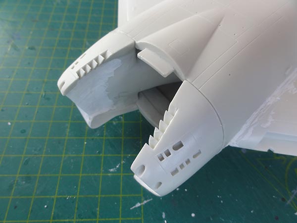
The intakes and areas were painted white on their insides.
On to next [ Page 2 ... ]
References:
Books and magazine
- Cutlass, "Naval Fighters" series number six, Steve Ginter, 1982
- Air international magazine: Vol. 43, pages 270...;
- International Air Power review, Volume 15, pages 98... , AirTime publishing, 2005
Internet:
Back to 1/32 Models
(c) Copyright "designer"/ All rights reserved. Your comments are welcomed by webmaster
Created this page March 16, 2020