Fisher Model and Pattern
[ page 2 ]
F7U-3M Cutlass in 1/32 scale: building the Fisher Model and Pattern kit
CONSTRUCTION STEP PAGE 3 and PAGE 8
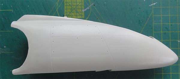
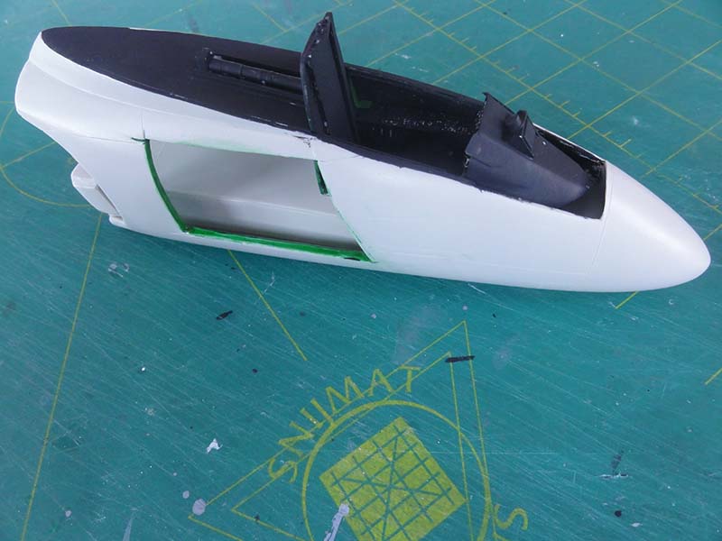
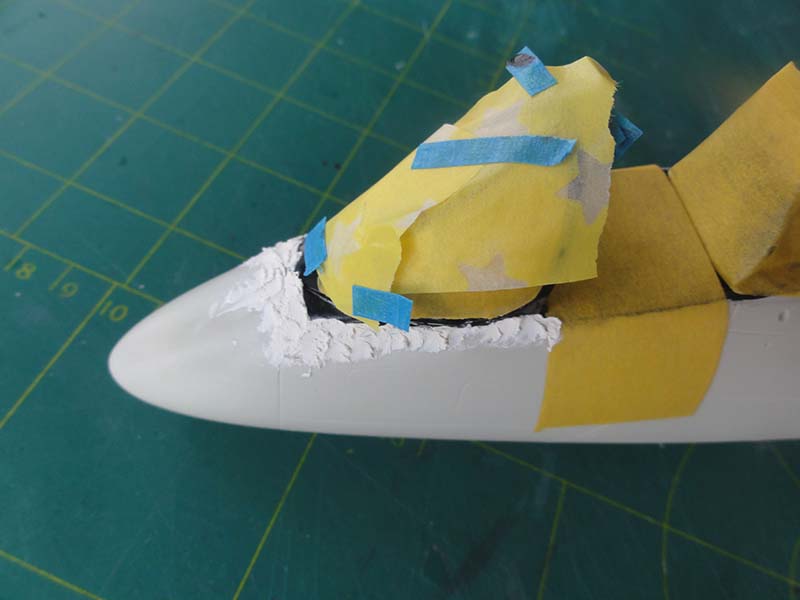
The nose section with cockpit is next.
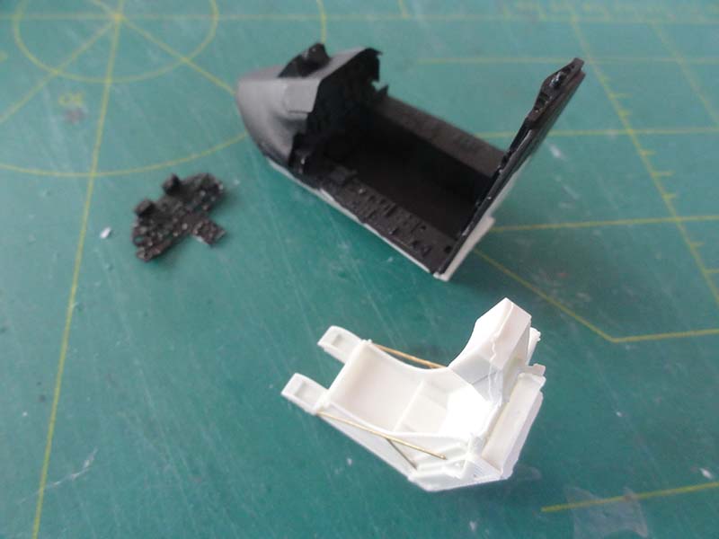
To add some more interest to the model an avionics bay hatch will be positioned open. With a razor saw a the hatch on the right nose side indicated by the panel lines was removed. The material is quite hard and thick so I managed to oooops... break the saw... .
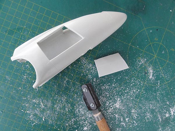
Inside from card a compartment was made, the avionics details and boxes will be added much later.
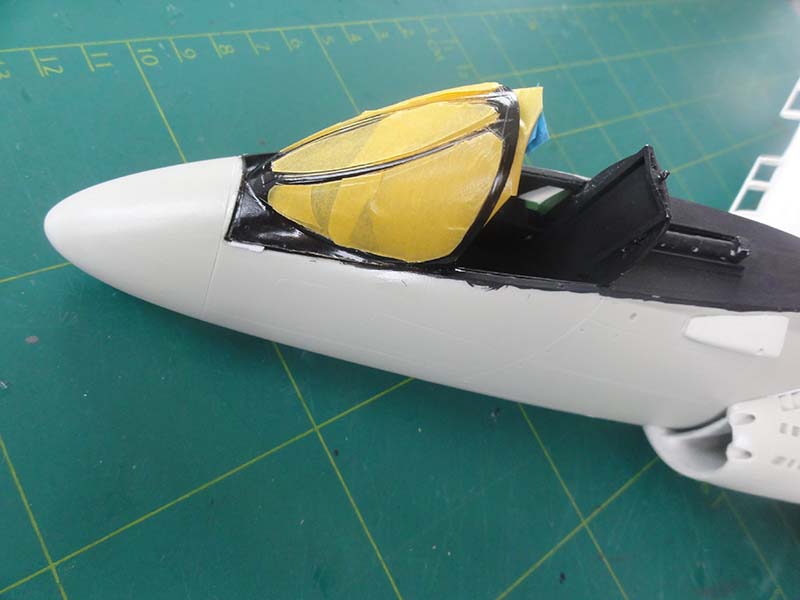
Now it was time to look at the pilot's office.
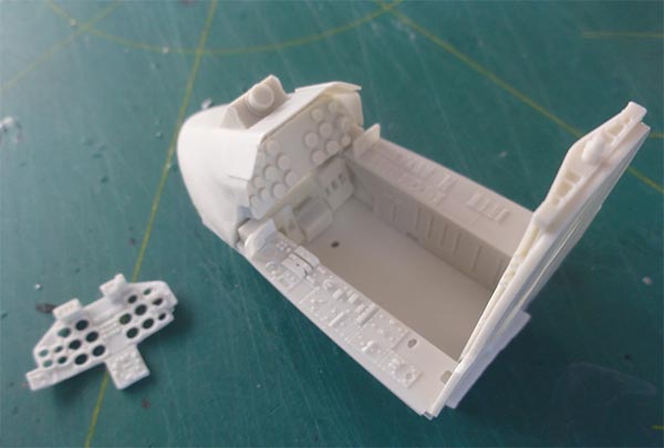
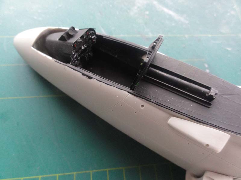
The cockpit instrument panel in the kit has several parts including the instrument housing and decals for the instruments. It is a sandwich type of assembly. Also raised detail is there but I could not find a throttle...
The ejection seat has several parts, I used the etched fret parts and the seat will be detailed more at a later stage.
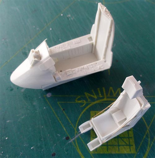
The cockpit interior colour is mostly black and this was airbrushed. (On old US Navy aircraft say before 1954 colours often varied with black upper areas and panels and zinc chromate green lower areas, but this varies. On many later US Navy aircraft, the cockpit interiors were black with medium gray).
A gun sight will also be added later on. (Cockpit equipment varied a bit between aircraft, certainly for VX-4 test squadron depending on tests being done).
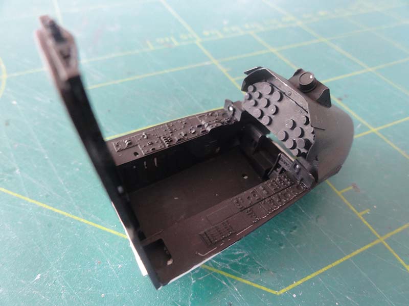
Details were painted with a fine brush in various colour dots, based on the flight manual illustrations, see scrap page here....
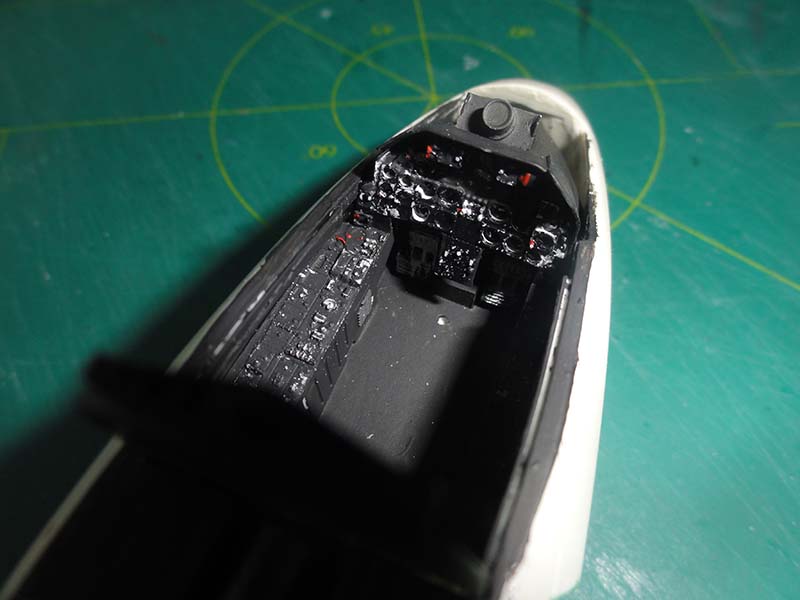
Fitting the cockpit inside the nose is no problem when a little material is shaved off the nose bay part. No extra nose weight is needed as the model will sit nicely on all 3 gear legs.
Some side edges were also painted black.
More details will be added to the cockpit at a later stage, such as a throttle.
page 1
page 2
page 3
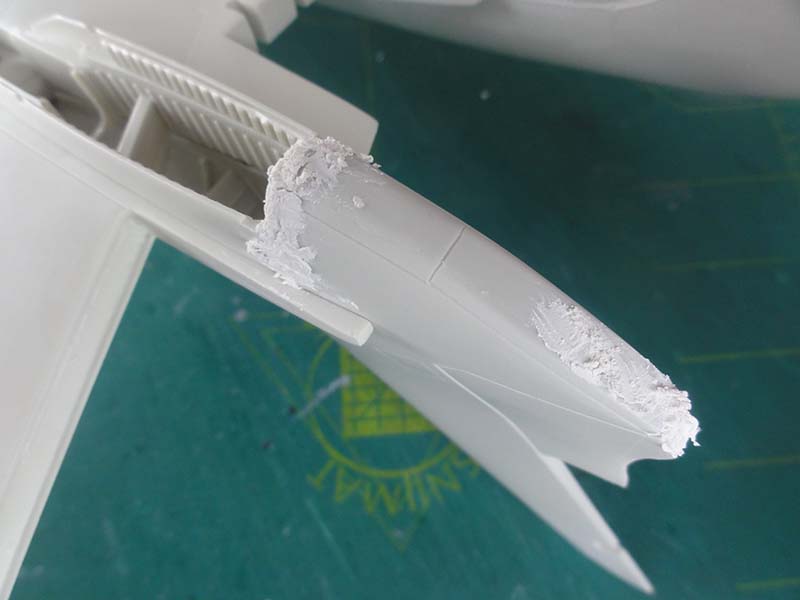
Joining the nose to the main airframe section is no problem.
Some plastic card on the inside to act as lips was used to get stronger joints with the two component glue and some filler does the rest. Take care to align well and have a symmetrical fit. Note the pencil marks to help alignment.
Some additional filling is needed. Some thin card was set next to the air vents of the intakes.
For the lower joint assembly was no issue. Some sanding is only required to get a good result.
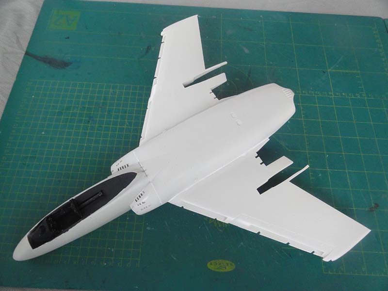
Now the assembly looks more a Cutlass... (The wind shield will be added later).
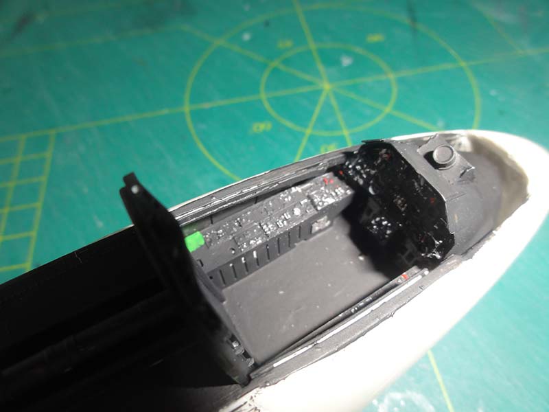
The small fairing next to the cockpit opening was set, some white glue was needed to close the gaps. A small fairing on the nose is indicated in the instructions. I could not find it so made it from sprue the part looking at photos.
STEP PAGE 5
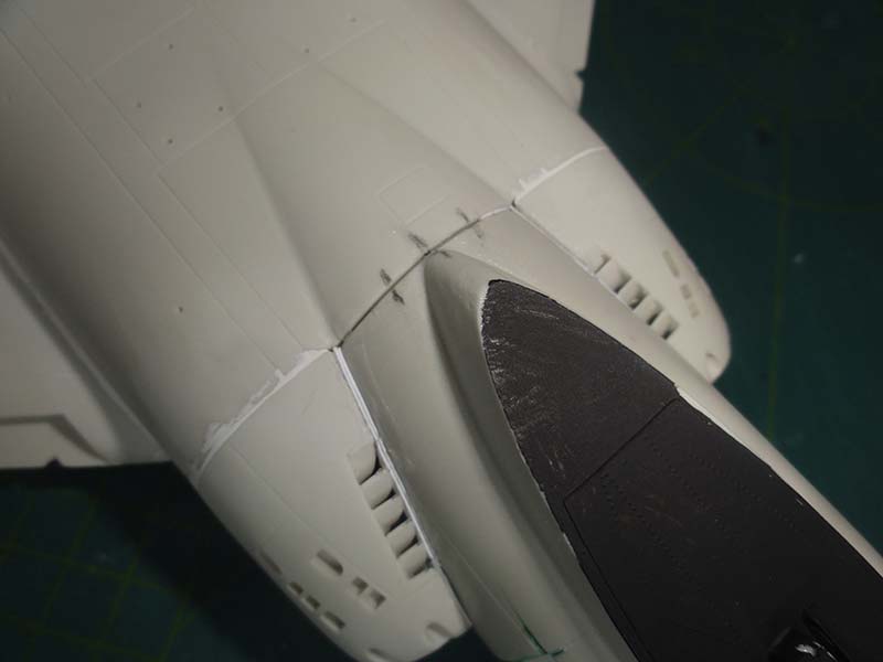
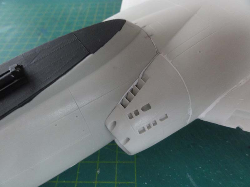
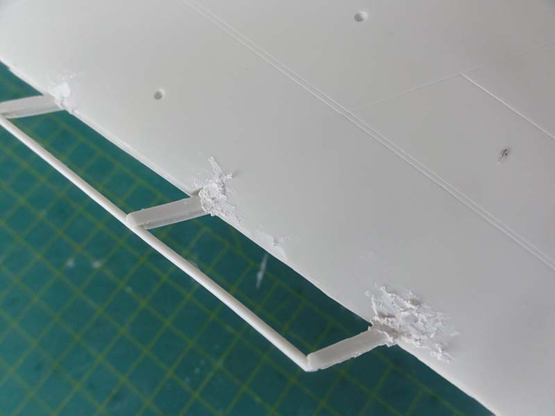
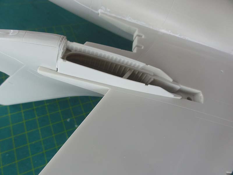
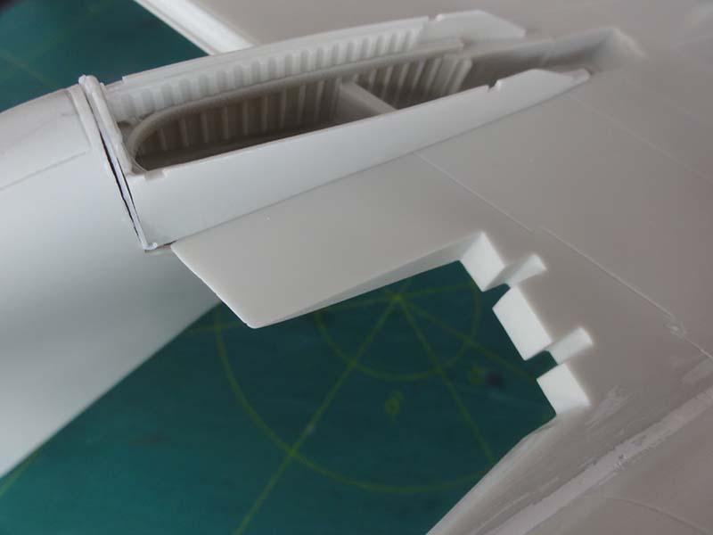
The next steps are setting the leading edge slats inserts. This needs some more work than on previous steps.
I needed to reduce the length by some millimetres the insert parts to get them to fit. Also, at the lower inside edges, same material was removed. Note that the "rods" will fit inside the leading edge slats.
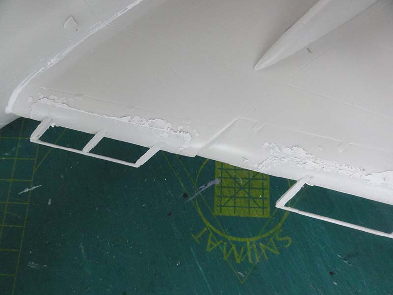
The slat rails do not align completely correct with the slots but I did not bother as most will be hidden when all is assembled. The inserts also need some sanding and filling.
Some tiny bits were set in the slots and filler will follow.
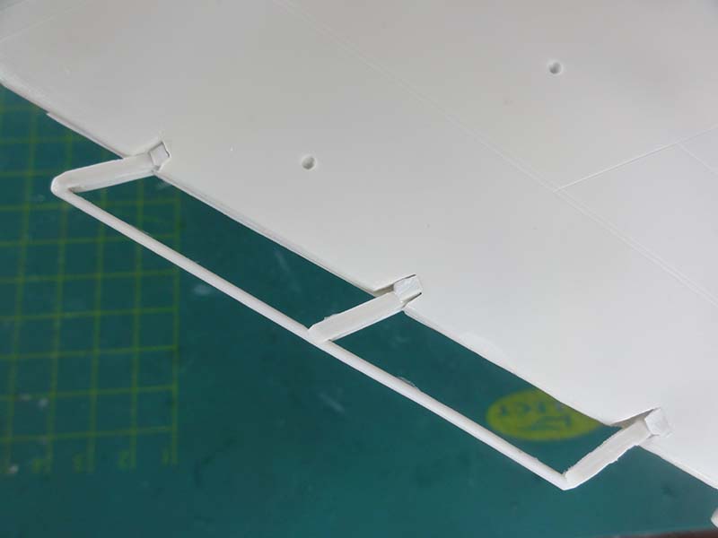
The small gaps filled as seen here and to be sanded.
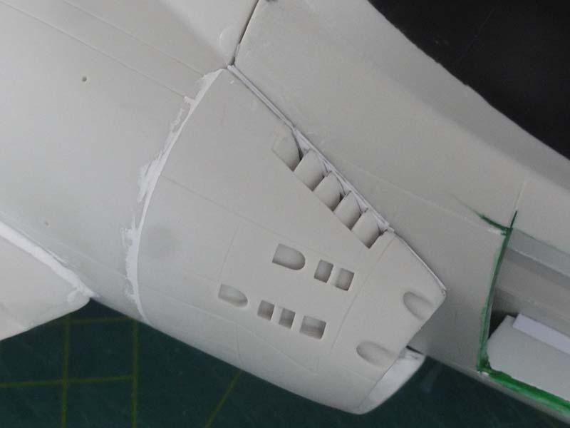
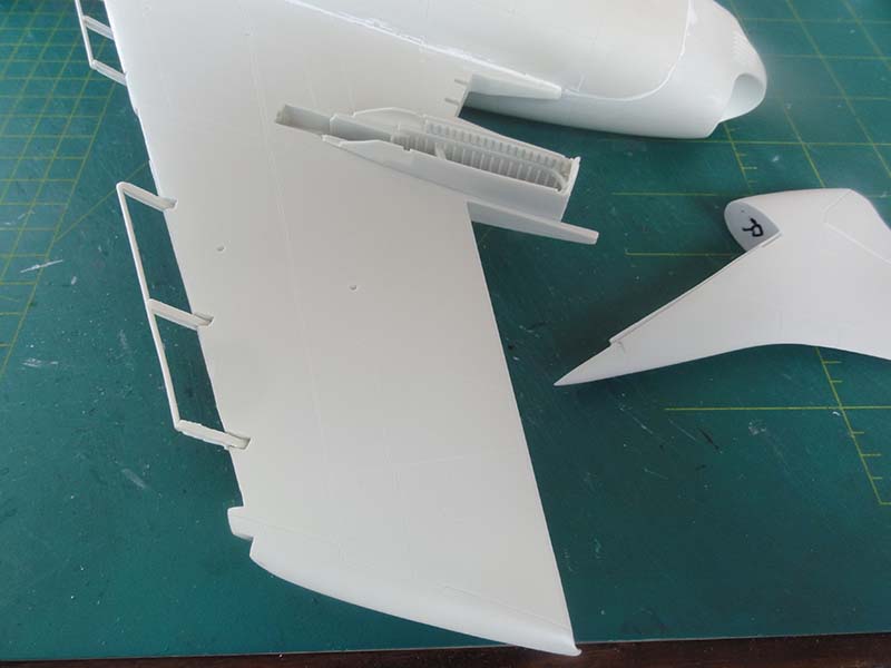
The next steps are fitting the main gear bay parts and the two vertical tails. Some cutting and dry fitting is needed but indeed it can all be installed with ease. These are quite impressive parts with also stringer details. Ensure not to mix up left and right handed parts. I marked these with a permanent scriber.
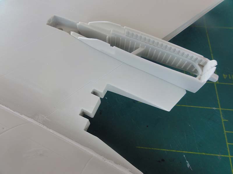
I added a piece of card aft of the left bay bulkhead.
Some putty was needed as well. Some thin card, filler and white glue will do.
For the vertical tails, ensure they are aligned vertical and use strong two component glue.
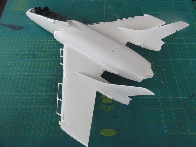
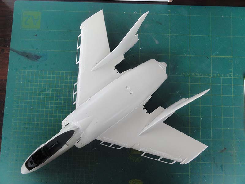
(The speed brakes are not yet installed)
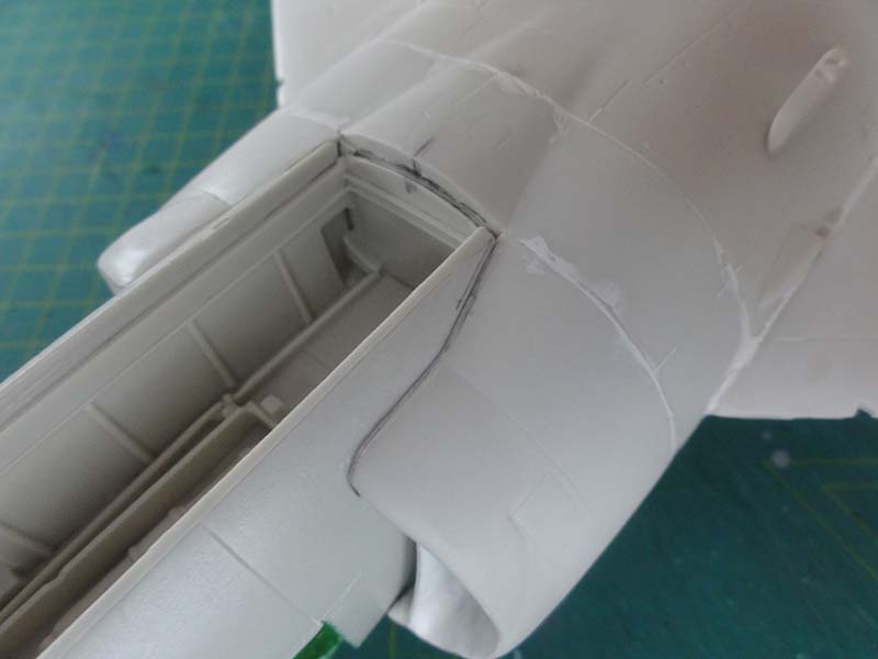
The rear canopy section needs removal of mould edges. Really be careful here not to crack the clear part! I used a very fine razor saw. Again, take care here!
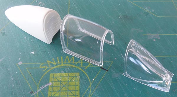
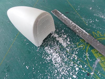
The rear fairing edges needed quite some sanding to make them deeper in order to get a flush fit of the clear canopy section.
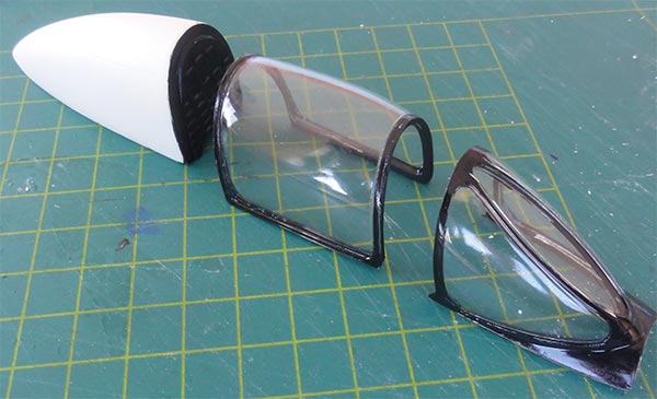
At this stage, the inside frames were painted black of all clear sections. The rear canopy section is not yet fixed.
The front wind shield was now set in place. There are some gaps. I added a thin piece of card to raise the wind shield part at the front and have a flush joint.
Some filler was needed to close the gaps but first the clear areas were protected and masked. Sanding did the remaining job.
STEP PAGE 6 and PAGE 7
The undercarriage parts are now to be prepared. The strong main gear legs moulded extensions were sawed off as indicated.
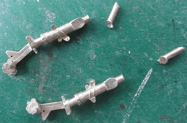
The smaller parts were set in place. I could not identify all of these, I presume that some extra parts were supplied in case the "carpet monster" swallowed some of those....
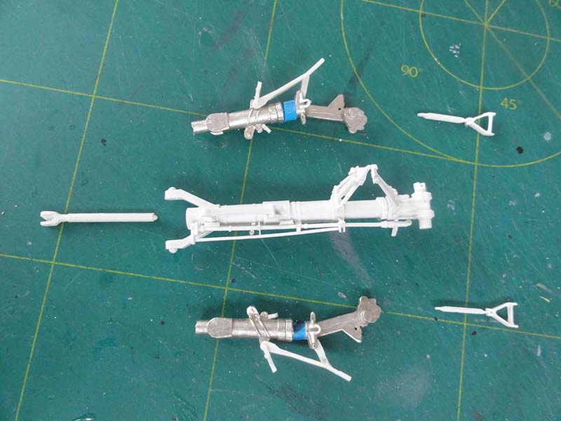
The oleo section was masked off and will not be covered with paint at a later stage.
STEP PAGE 10
At this stage, turn to the "ailevators". Etched metal trailing edge frames are provided. bending these straight is quite difficult but these are typical for any Cutlass.
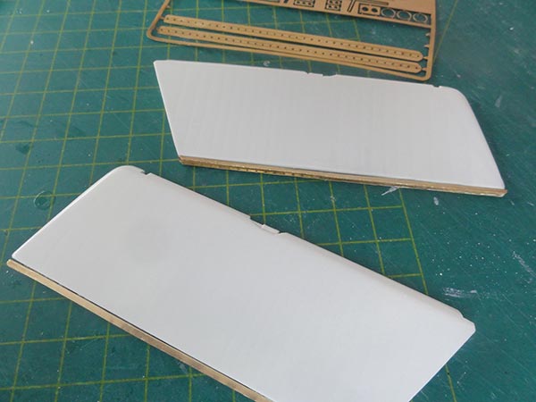
I also drilled in each ailevator 2 holes and 2 corresponding holes in the wing to accept a pair of metal rods to add strength. The ailevators are often seen slightly or more drooped on parked aircraft.
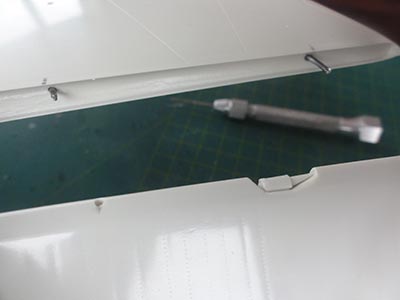
The slats and ailevators were NOT yet installed, painting is to done first.
(on page 10 also the gun blast deflectors are shown, leave for later).
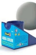
The Cutlass is now overall ready to get a first grey base primer coat. The smaller parts also need a bit of base coat so will be prepared as well. For the base coat I often use Revell acrylic 75 "grau" that covers well when applied with the airbrush.
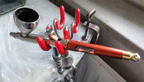
Any airbrush will work, I use a Harder and Steenbeck Infinity.
On to next [ Page 3... ]
Back to 1/32 Models
(c) Copyright "designer"/ All rights reserved. Your comments are welcomed by webmaster
Created this page April 14, 2020