Fisher Model and Pattern
[ page 4 ]
F7U-3M Cutlass in 1/32 scale: building Fisher Model and Pattern kit

... continued from page 3....
BACK to STEP PAGE 10
The slats were now set in place. That was more difficult than expected. A few slats were about 3 millimeters too long in span. With a razor saw a few millimetres were sawed of in parallel with the air flow. Small air flow gaps/slots between slats and wing are seen on aircraft. I glued tiny bits of rod insides of the slats to ensure a gap and have extra fixation area for the glue. Setting the slats symmetrical on the wing was not easy.
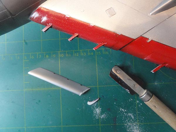
The ailavators at the wing trailing edges were also set in place. As noted earlier, their fixation was improved with metal pins fitting in drilled holes.
page 1
page 2
page 3
page 4
page 5
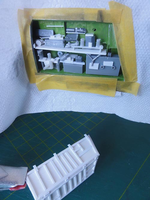
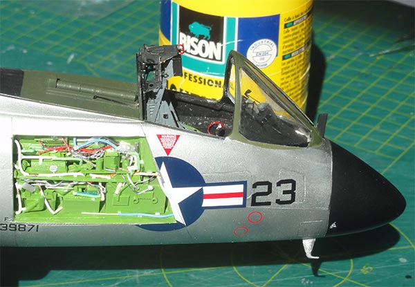
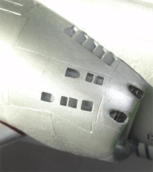
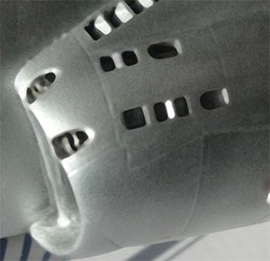
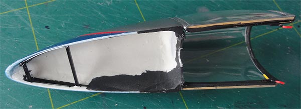
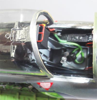
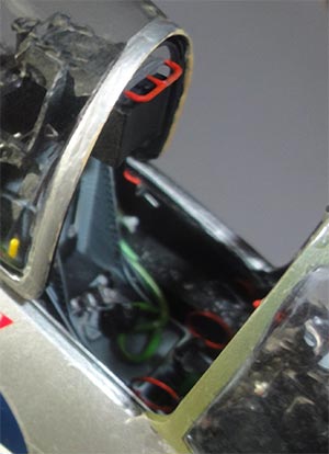
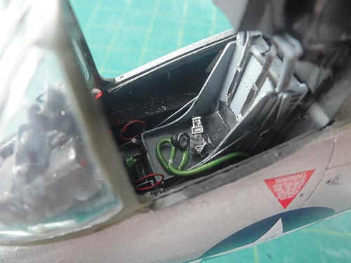
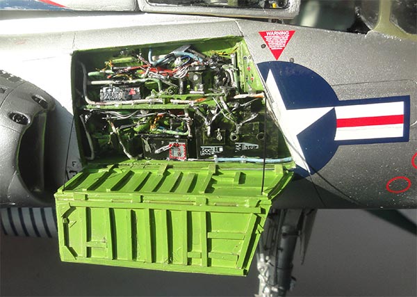
The smaller bits in the avionics bay with various boxes were now added and made from scrap based on a few photos in the Ginther book op pages 48, 89, 90, see references. This is done now as the model can still be handled easily. White glue was used to suggest fixing latches.
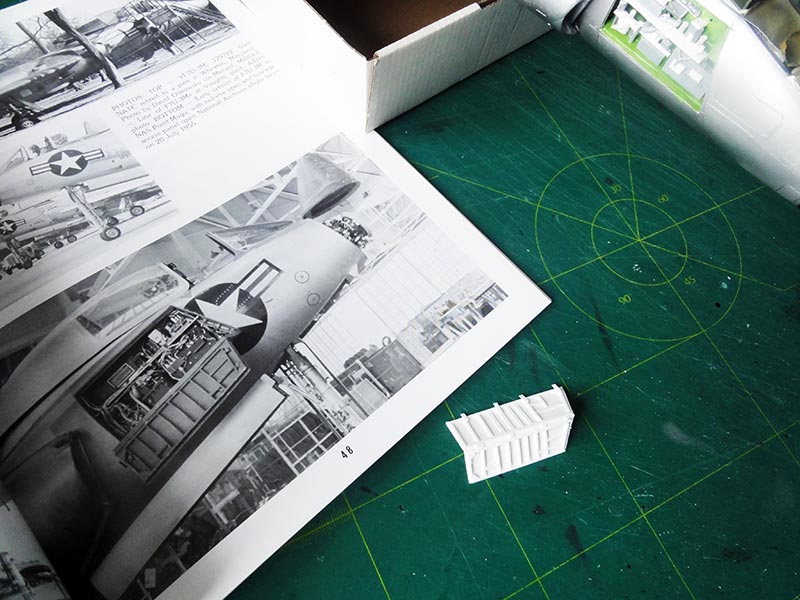
The two hatches were also detailed. They are hinged to each other.
Adding bits and pieces from scratch.... More to follow...
STEP PAGE 9: LANDING GEAR
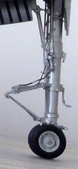
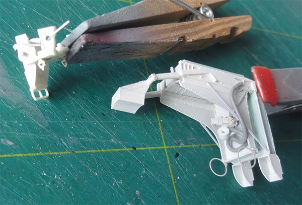
Installing the two metal main gear legs and the resin long nose gear leg gave no problems into their locating holes. The nose gear leg sits at 90 degrees relative to the ground. The main gear hubs are 2x2 parts, remove the central lug to fix them to the dark grey/ tyre black wheels.
The wheels and hubs fit well to the gear legs. Make sure the legs and wheels are at 90 degrees to the ground.
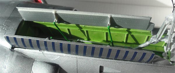
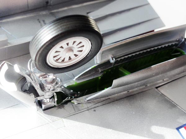
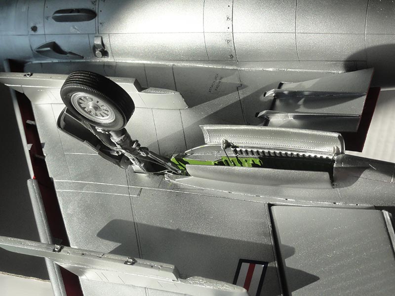
Installing the gear doors needs careful alignment. The "U shaped" retraction arms on the nose gear are not long enough, I made new ones.
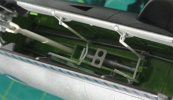
The insides of the gear bays and on the gear legs show various hydraulics lines / pipes and electrical wires. These were made from wire and stretched sprue.
Added to the nose gear were as well:
- a nose gear leg lock grip on the rear of the nose gear leg
- a small lever in front of the nose gear leg that hangs over the oleo section
- on the central nose door in front of the nose leg add the 2 tiny retraction rods as well.
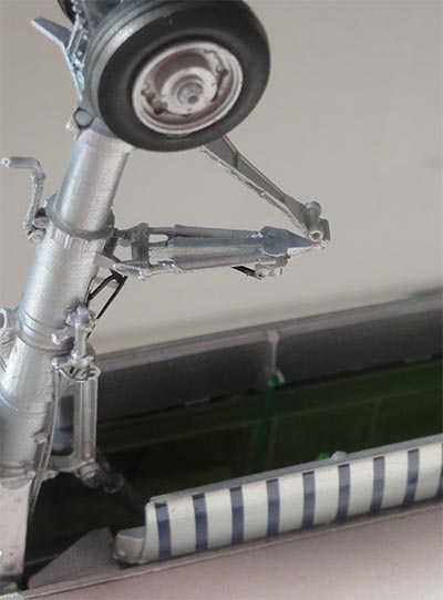
The main gear legs also got various hydraulic lines and wires from scrap. Inside the bays also some were added. The doors were fitted without any problem but some rods were installed for the mechanisms.
STEP PAGE 11 and COLOUR PAGE
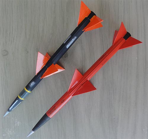
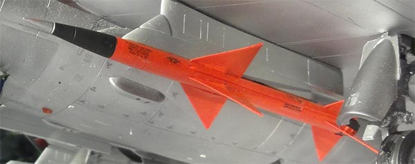
The Sparrow missiles were made. Four are provided and can be finished in different paint schemes. I made a few in different schemes:
- One missile paint scheme suggests yellow missiles but photos suggest these to be quite orange. I airbrush Gunze Sangyo H339 orange and for the bodies black;
- Another missile paint scheme were mostly orange missiles.
Fisher provides nicely also stencils decals for these.
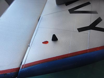
The various fuel dump pipes (3 of these) and 3 wing tip An/ARR-2A antennas were set.
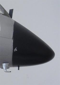
The barrier guard on the wind screen set and also the single pitot below the nose. The pair of pilots access step bars (with open canopy set) were installed.
On the lower nose of the VX-4 Cutlass "139871" in the natural metal scheme I also saw a tiny black antenna on the lower radar nose radome. This was added from card.
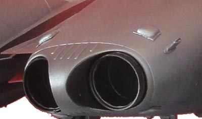
The burned metal painted exhaust pipes at the fuselage rear were also set in place with no problem as their holes were scraped a bit at the beginning of the fuselage assembly. A small section remains visible.
The arrestor hook was painted metal and got 2x4 black striped sections. It was set in place.
The very tiny gun blast deflectors (seen FISHER STEP PAGE 10) were installed. Each one has 2 halves and are a bit small to align and add. You get extra halves in case some disappear in the carpet monster. Each gun port has 2 blast deflectors. Paint them metal.
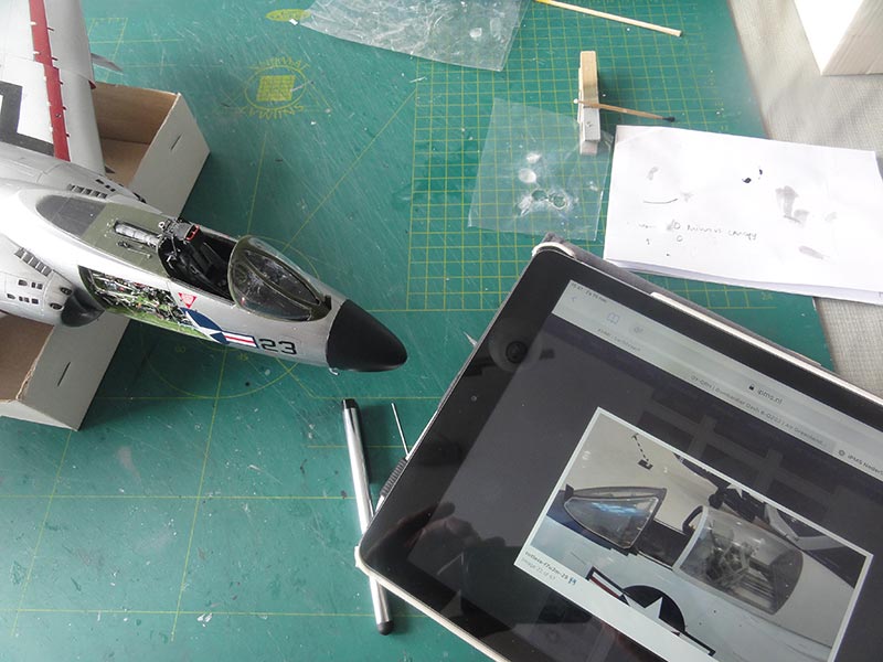
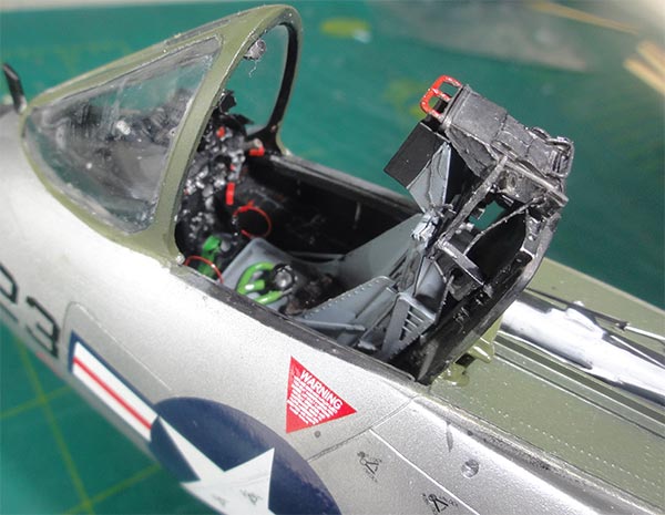
Adding extra details is worthwhile in 1/32 scale. The IPMS.NL walk around (see references on page 1) of my modelling friend Cees is very welcome here. This shows a lot of the smaller details of the Cutlass. So do a walk around of your model and looking at the photo walk around!
STEP PAGE 8
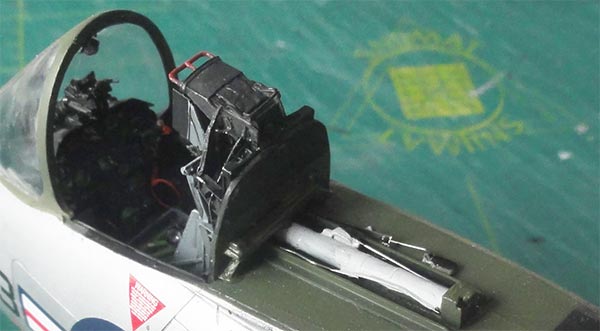
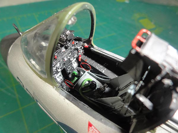
The ejection seat is nicely provided in the kit. The Cutlass had different types but the "later style" is in the kit. I added details based on the drawings seen on the "scrap page":
- small wires and cables in the head rest area
- sort of safety pin no.6 on top of the firing tube
- 4 seat straps with buckles
- oxygen hose and tube (resin kit part)
The forward area of the seat head rest was painted black, the seat medium grey with black details. The braces handles provided in the kit in etched metal were painted red.
The seat curtain handle on top (also in the kit in resin) was painted also red.
(sorry, I forgot to make a separate photo of the painted seat).
The clear canopy was now fixed to the rear fairing/ hood. A clamp is needed to hold it in place while glue dried. I than filled the seam with putty and sanded it after protecting the clear section. (I later found the canopy needed some "pressing" in order to fit over the seat assembly later on. But it can be set in place and stays there).
Inside the sliding canopy and its fairing I installed a few structural beams based on the walk around photos and the "cockpit canopy / hood" drawing on the "scrap page". The canopy frames at the transparency and of the insides wind screen are black. I added the pair of canopy roller locks and painted the rubber seal gasket moulded at the front frame brown.
NOTE: Fisher indicates that also 2 rear view mirrors (provided in the etched metal fret) are to be mounted. But I could not find any photos that show these, so left them out.
The canopy hood is kept detachable from the model for cleaning and transport if needed.
Further cockpit detailing is next....
There is a sort of gun sight in the kit but I saw on many photos that also another quite larger type was used. (The Ginther book shows it at their page 43 ). From some bits and rods this was made. I also added a bit of plastic, what is probable a standby compass, in the wind screen frame top. On some aircraft this standby compass is set on top of the instrument coaming.
Inside the cockpit, smaller bits were also added (see the cockpit drawings on the scrap page):
- the kit control column was installed
- to the rear lower base of the seat bulk head an an extra curved frame.
- near the canopy sliding actuator various hydraulic lines and control wires; the actuator was painted medium grey.
- the various floodlights below the cockpit sill left and right sides
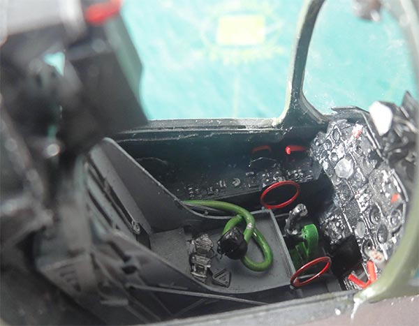
Left side:
- the engines throttle levers no.11
- the oxygen hose on the left side console near the seat
- emergency canopy control handle no.17
- landing gear control handle no.19
 .
. 

-
Right hand side add-ons:
- arresting gear control handle no.4
- console flood lights
STEP PAGE 12 and EXTRA DETAILS
The 2 rudder actuator rods on the vertical fins were set in place as provided in the kit. Note that there are not symmetrically fitted.
Some tiny lights in clear resin are provided in the FISHER kit but could not be found in the instructions. These are very difficult to find on the old black and white photos of those days. I discovered their purposes and locations in the manual of the aircraft, some drawings shown in my "scrap page".
The "exterior lights" drawing with numbers shows:
- an upper fuselage light (no.7)
- 2 lower formation lights (no.11) on the lower wing tips in both side
- a lower fuselage light (no.16), the exact position is difficult to see.
- the 2 aft fuselage lights (no.8 and 9) could not be seen on walk around photos so I did not add them.
Also shown is that the LF (left hand) wing tip light is Red and the RH (right hand) light is Green.
The model is now largely completed but as it is 1/32 scale, it is worth to check out any smaller details that may be added:
- on the lower fuselage I added tiny plastic bits such as a small drain pipe aft of the arrestor hook.
- a small intake on the side near the wing root.
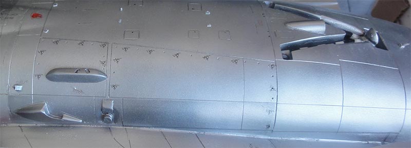
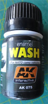
Some AK wash was applied over the gear legs, some panel lines and some other areas. Any wash technique will work, but do not over do it, these Cutlasses were well maintained as Navy planes.
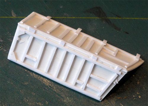
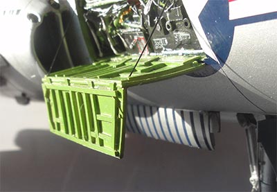
The opened up equipment bay access door was set in place. It has 2 chords on the real aircraft as mechanics use them as platform.
That completed a very nice large scale F7U-3 Cutlass!
MORE PHOTOS on next [ Page 5 ... ]
Back to 1/32 Models
(c) Copyright "designer"/ All rights reserved.Your comments are welcomed by webmaster
Created this page May 26, 2020