[ conversion page 4 ]
1/32 conversion to build a T-45 Goshawk US NAVY jet trainer
..... back to page
3...
CHECK OUT FOR COCKPIT INFO MY OWN T-45 INFORMATION PAGE
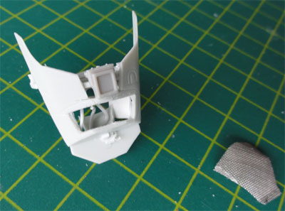
Some things were done for the cockpit
details. On the T-45, the coamings (parts # 11, 12) have a different shape.
Also, cooling grids are seen. These were cut open and made from metal mesh.
 .
.
The T-45 instrument panels were completely
changed, with card with drilled holes, strip and stretched sprue. Study
photographes of te real thing.
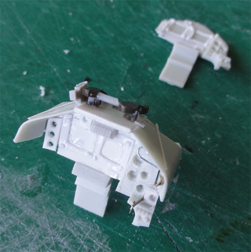
On the cockpit sidepanels and instrument
consoles, details were also added.
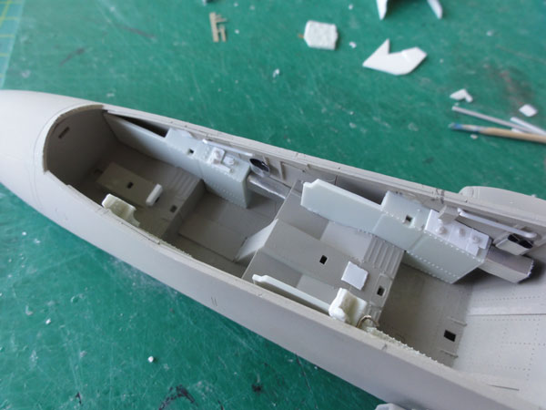
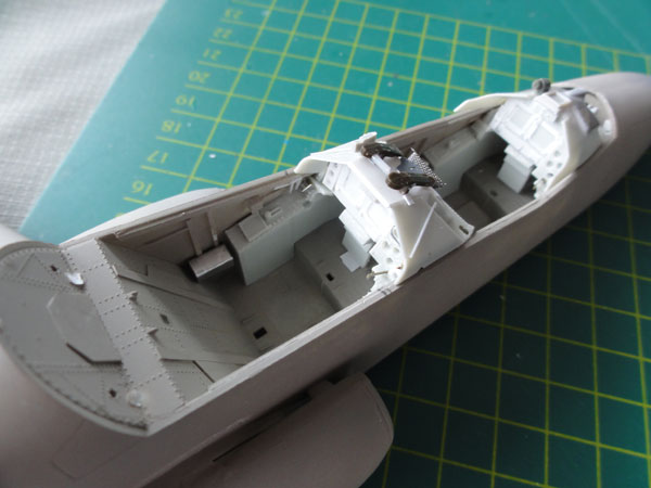
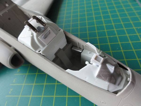
( The detailling of the new different
NACES seats is done later ).
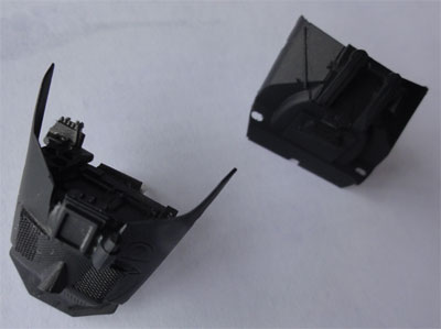
The coamings got a black mat coat
with the airbrush.
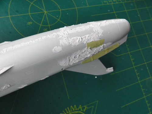
The fuselage was further prepared
with putty and sanding. Here the rear end is seen, with the closed airbrake
area of the Hawk and improving the curve at the exhasut pipe.
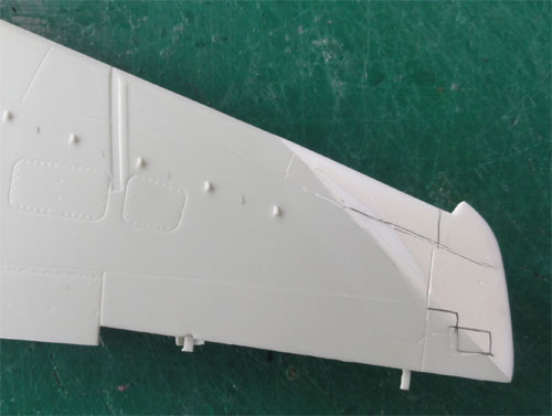
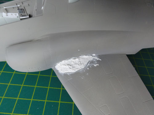
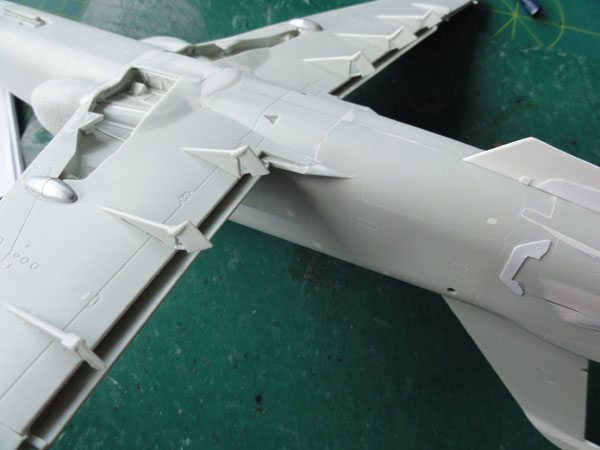
The wing was also puttied and sanded
as a separate assembly. NOTE: the bulge next to the main gear bay is a
movable part! It opens up when the gear is down (so not fixed glued
on here).
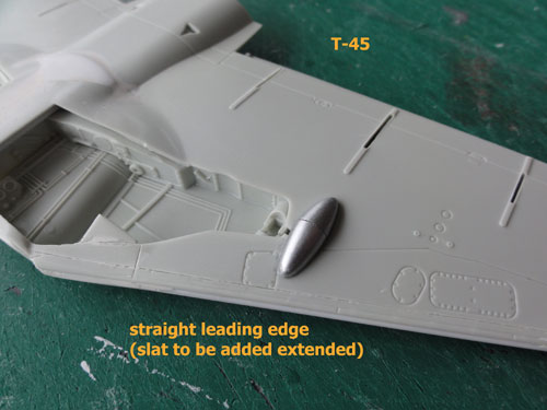
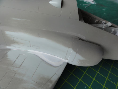
Here, the wing tip change is also
seen for the T-45. The fence is not on a Goshawk, so also needs further
filling.
On the upper wing, the slat recess
area will be suggested with a red paint leaduing edge, to be done later.
The main assembly was done setting
wing to fuselage.
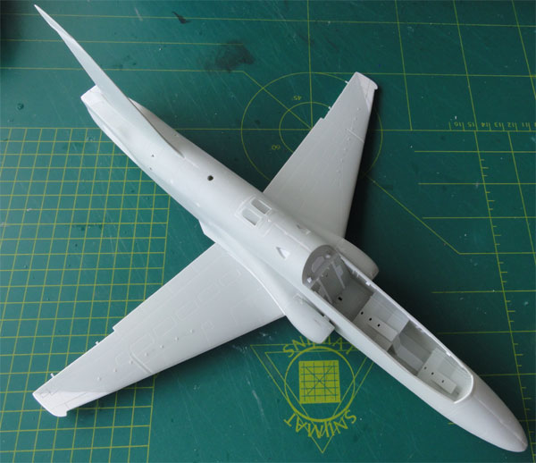
The gaps were filled and some work
is still to be done...
The assembly was given a light grey
primer coat with the Airbrush to check for any irregularities. These were
corrected with putty again.
F- (bumped fairings upper wing-root)
The wing fuselage joint has also
a bumped fairing on the upper wing-root area (thanks to Daniel who informed
me on this). (on the Kinetic 1/48 kit these are missing as well).
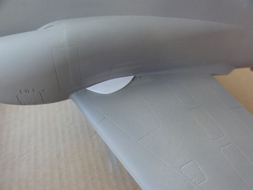
These bumps were made with card and
putty. Sand in shape.
These are very subtle but important
details.
Here on the right hand side wing.
STEPs 54- 55
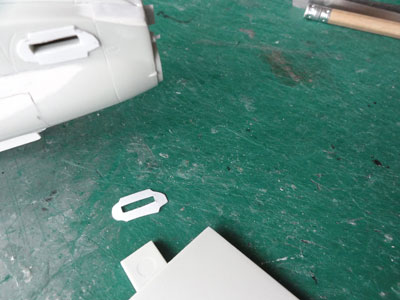
The upper fuselage intake scoops
(kit parts #52 + 53 ) are also seen above. These were reduced
2 mm in length at their forward edge This looks better as compared to the
real scoops. Antenna #119 and parts #115, 116, glass 51 were not fitted
on the T-45. The nose pitot #120 will be used but fitted at a later stage
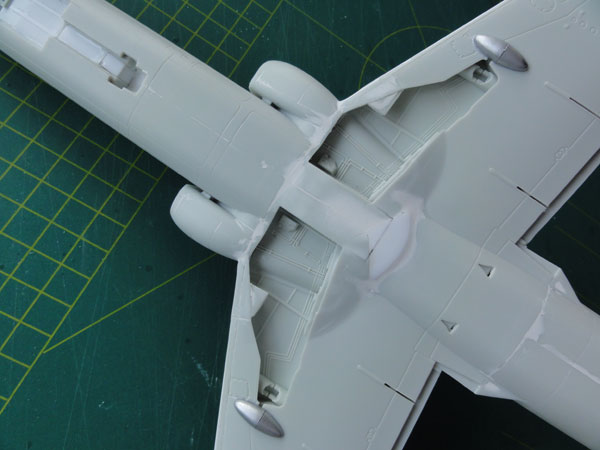
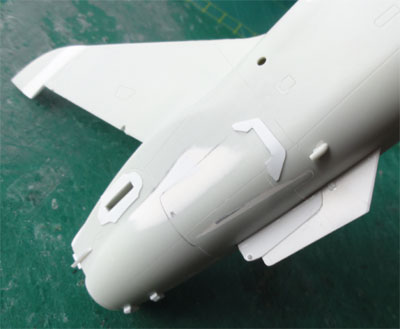
K- single ventral fin (with arrestor
hook)
The T-45 has a single ventral fin.
This was made from thick card and sanded in shape.
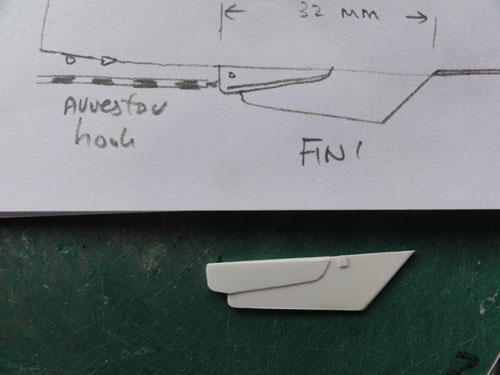
A sort of end-plate is seen at the
horizontal stabilizer, this was made from very thin card:
STEP 20
The kit ailerons were simply assembled
but not yet fixed onto the model. The leading edge fences (parts 384) are
NOT required for the T-45 Goshawk.
STEP 21
The wing assembly was discussed on
previous pages. flap hinge fairings (parts #81,82,83) were adapted to accept
a drooped trailing edge flap as always seen on a parked T-45. This is quite
some work. The kit parts were cut and a rod added for the actuator.
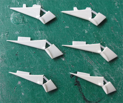
The hinges are seen here set on the
lower wing...
STEPs 23-24 and STEP 27 for the larger
horizontal stabilizers were already described
on page 2....
They were not yet fitted though.
STEP 55
The upper scoops #53, 54 were reduced
2mm in length. Next they were fitted on the fuselage spine. (The antenna
#119 was not used).
A base coat of very light grey was added again with the airbrush in areas to check for any flaws.
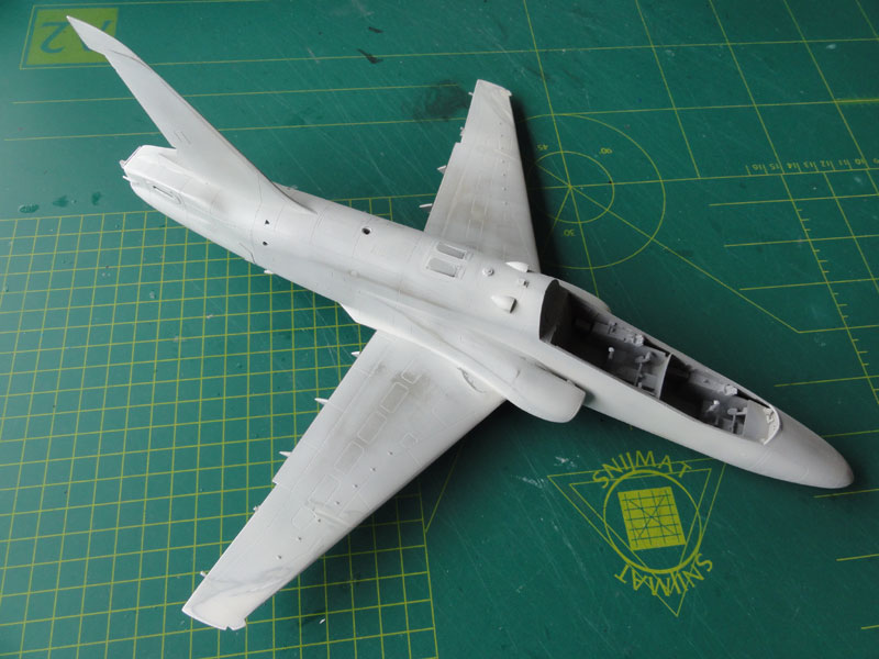
*(note: the extra wing vortex
generators of the T-45 are still to be added...)
On to next [ page T5 ....]
Back to 1/32 Models.......

(c) Copyright Meindert "designer"/ All rights reserved. Your comments are welcomed by webmaster
Created this page
June 16, 2013