[ Page 1 ]
1/32 scale Infinity Models De Havilland Vampire model
page 2
Vampire trainer report
..
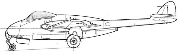
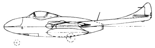
an early Vampire side view
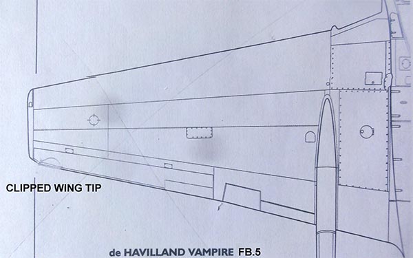
The F mk.3 (or F.3) version was the single seat fighter with an improved canopy with some 220 manufactured. The FB mk.5 (or FB.5) was the fighter-bomber version especially envisaged for ground attack and had the possibility to drop about 1000 kilograms of bombs and rockets and could carry under wing tanks. It still had the Goblin 2 but got reinforced wings with 2x1 ft clipped wing tips resulting in a smaller wing span. As it was heavier it got a modified longer stroke undercarriage. Over 1,100 FB.5 were manufactured. Plans to fit the FB.5 with ejector seats never materialized (this experience was used for Venom development with a new wing.
Vampire two seaters with different fuselage were developed as well. It started with night fighters "NF" with a radar operator/navigator in a "staggered seating". A later developed two seat trainer was the T.11 with also weapon trainers like the T.35 with "side by side seating" and new canopy.
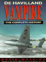
Tip: may I recommend the Vampire "Complete History" book of David Watkins (see references..)
See for more history information the 1/72 Vampire pages here...
In 1/32 scale there was for many decades only a rudimentary vacuform Vampire that was made in the seventies by Alan Dent, later brought by Dough Feeney ID models and the same moulds again later by "Tigger". This basic vacuform I still have is shown here:
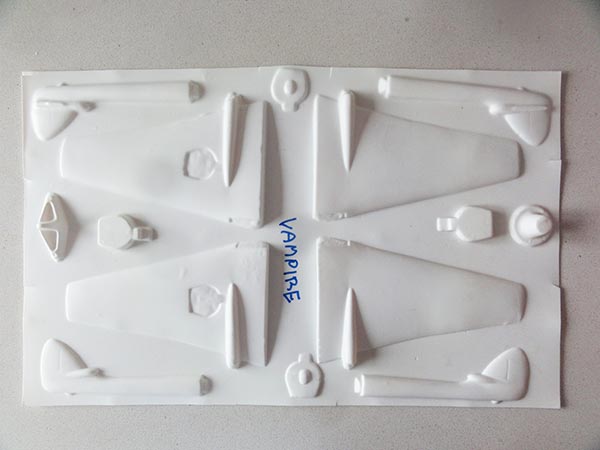
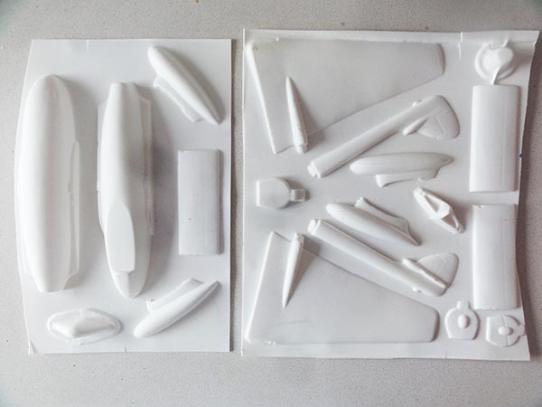
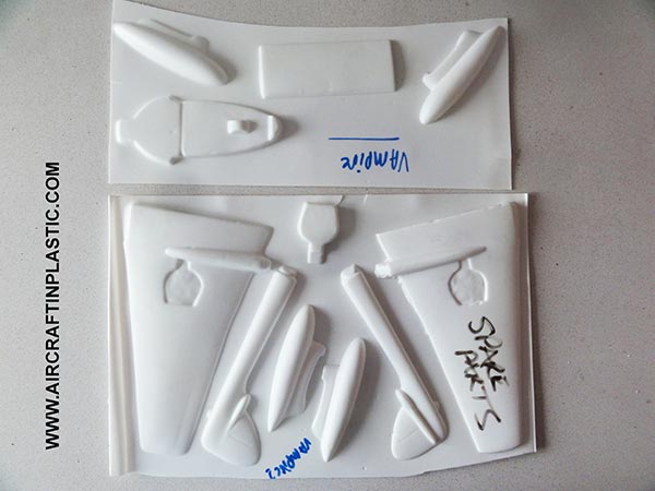
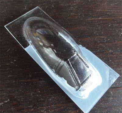
Making this vacuform would take a lot of effort.
INFINITY MODELS VAMPIRE
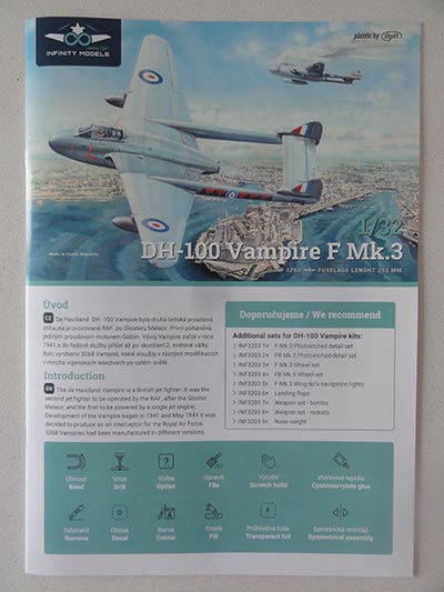
But thankfully, in the Summer of 2022 Infinity Models from Czechia released 2 Vampire injection moulded kits in 1/32 for a F mk.3 and a FB.5. Infinity is a new brand of HPH that made high quality models in resin and fiberglass. I had made their impressive 1/32 Aero L-29 and L-39 earlier.
Infinity brought 2 releases:
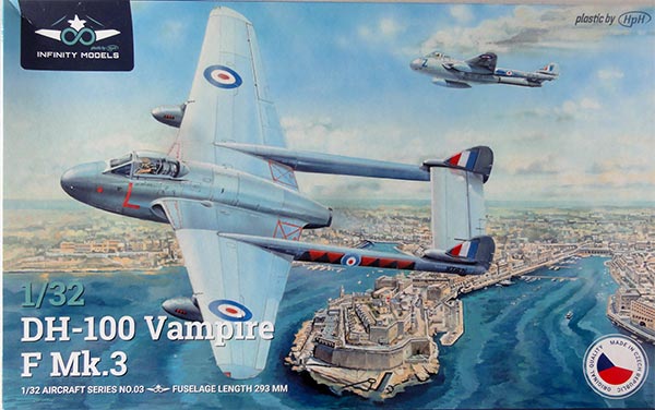
[1] Vampire F mk.3, kit 3203 with decals for a silver dope Royal Air Force 601 squadron also based at Malta, 1950s and silver dope a Royal Canadian Air Force 442 squadron at Sea Island, BC, 1950s.
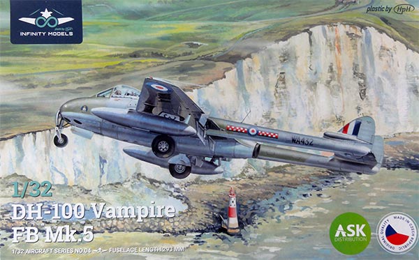
[2] Vampire FB.5, kit 3204 with decals for a camouflaged Royal Air Force "603" squadron, RAF Turnhouse, 1955 and a green-grey Swedish J-28B of the Flygvapet F11 wing, 1954.
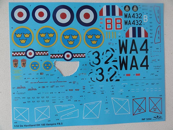
(note: instrument decal already cut out)
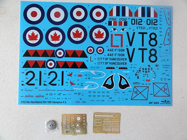
The kits have the same injection moulded parts but different and excellent decals. In the kit box are also 2 tiny etched metal frets with seat harness and a few airframe details. There was also a resin engine fan part but this is not indicated in the instructions nor necessary as it will not be seen.
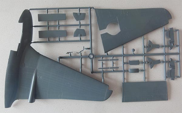
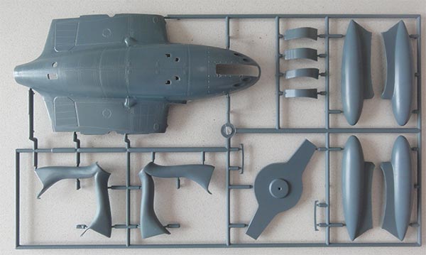
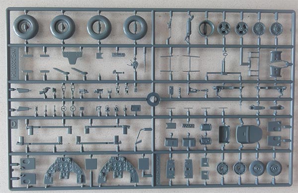
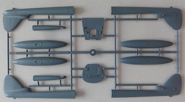
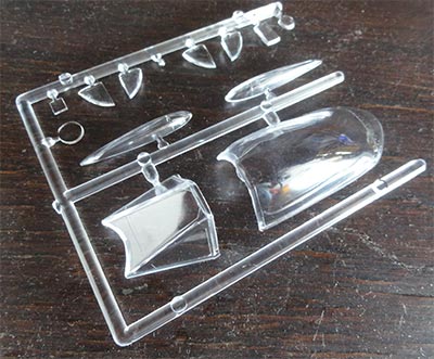
Parts lay-out:
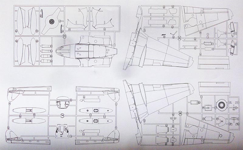
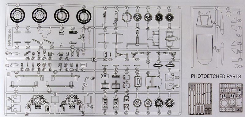
The kit has been designed with CAD, 3D tools and the details are good. There are no alignment pins though. The common sprues with soft grey plastic in both kits are seen here....
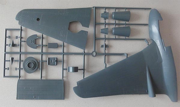
The transparant parts are really clear. The single seat canopy has a separate windscreen and canopy so can be set slided open if desired. It seems that very early Vampires had not a full frame around the rear sliding perspex canopy, later versions appear to have had frames.
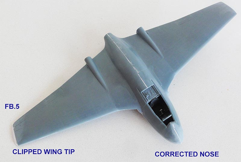
For the FB.5 one needs to "clip the wing tips" and install clear straight wing tips. Also a few other parts that are provided in the kit such as slightly different instrument panels and wheel hubs.
The Infinity kit instructions are very good with 43 steps and good decal guidance. Infinity suggests to buy separate aftermarket detail sets but these are not necessary though as the kit provides adequate parts. You don't get the unguided rockets but their rails are in the kit. The rockets may be found in the Matchbox/Revell Sea Venom kit.
(The aftermarket landing flaps set may be nice to have but than needs some surgery to separate and droop the plastic sections).
DOWNLOAD INSTRUCTIONS PDF
The major parts break down is a bit unusual as you get two halves with upper fuselage and wing halve moulded in one piece each. This will avoid a wing-fuselage gap and ensure a good wing angle without dihedral/ anhedral.
The kit has no alignment pins and needs a lot of cleaning-up the sprue gates to get smooth joints. The plastic is a bit soft as well but it has nicely moulded details.
The parts have engraved panel lines and a lot of finely indented rivets at the wing and aft fuselage. The patterns look well researched and seem to be correct. The Vampire had a wooden fuselage (based on Mosquito experience) between bulkhead 1 and 4 with the remainder airframe having a metal construction. Other parts like wing, tail booms and horizontal stabilizer were metal with flush rivets. The model has nice fine rivets at e.g.the wing which I think are OK. But if you want less visible rivets on your model, apply thin putty or thicker base paint layers.
ACCURACY
The 1/32 Infinity Vampire kit accuracy was checked up. I had various books about the Vampire but found it was difficult to find good drawings. When I enlarged a few drawings to 1/32, most drawings seemed inaccurate in places. The twin T.11 trainer had a similar wing as the Vampire FB.5.
So to check the wing planform, as other source, I checked it with the excellent 1/72 Airfix Vampire T.11 kit first released in 2012 and this release in 2018 seen here....
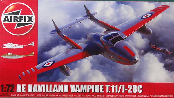
Airfix used scan technology for the kit. Measured lengths were scaled up from 1/72 to 1/32 by 225% (these are the blue lengths):
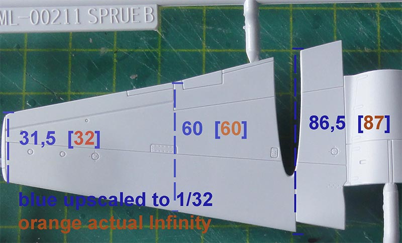
The 1/32 Infinity Vampire wing was measured (these are the orange lengths); it turned out that the Infinity wing planform looked accurate.
Seen here also on the drawing...
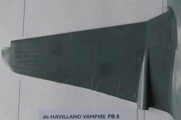
I think Infinity Models measured up or may be scanned as expected a real Vampire. Same with the rear lower fuselage, that looked OK too with nice raised streamlined fairings.
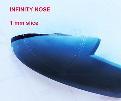
Looking at various photos, the forward fuselage side profile looked OK. But in top planform view looking at photos the nose tip looked a bit too blunt; this is obviously difficult to measure up on a real Vampire. (some photo parallax is obvious).
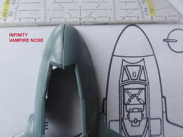
I concluded that a nose planform correction can be done to the kit by removing a section at both upper fuselage halves of 1 mm at the nose tip... so 2 millimeters in total, gradually running to the windscreen area and bending the nose a bit. Doing this extra effort while constructing this kit will improve the looks a bit and will be done....
Overall the Infinity Vampire kit has good details but the assembly of the main parts will require sanding and strengthening the joints.
I bought 2 Infinity kits in Czechia being inspired by the 1/72 Airfix Vampire trainer:
[1] - Infinity kit 3204 will be made as a Vampire FB.5 as described below; most suggestions are also applicable for the F mk.3 though.
[2] - the other kit will be cross-kitted with a Matchbox Sea Venom and converted to obtain a two seater Vampire trainer and a single seater Venom (to be presented in the future)
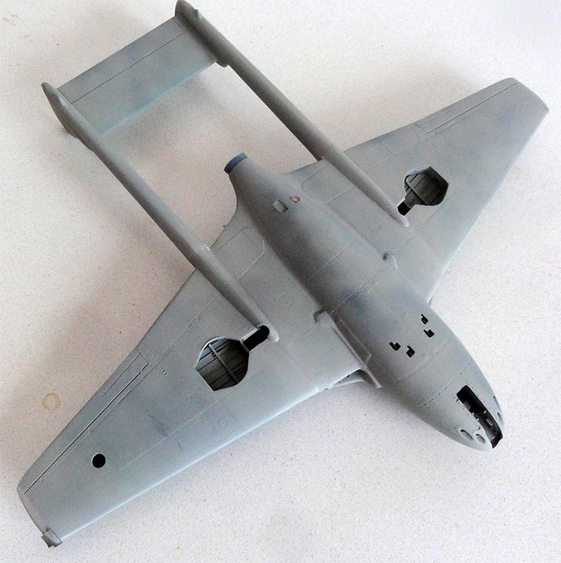
BUILDING THE INFINITY VAMPIRE
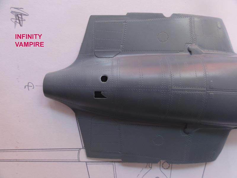
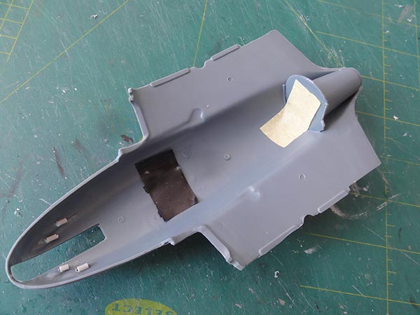
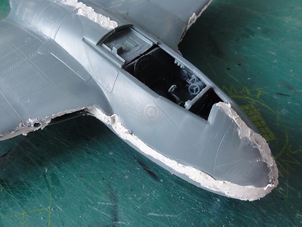
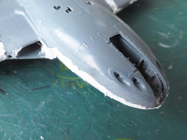
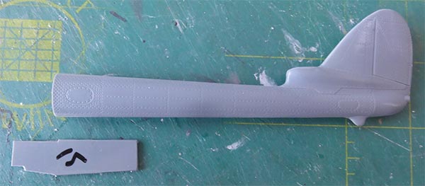
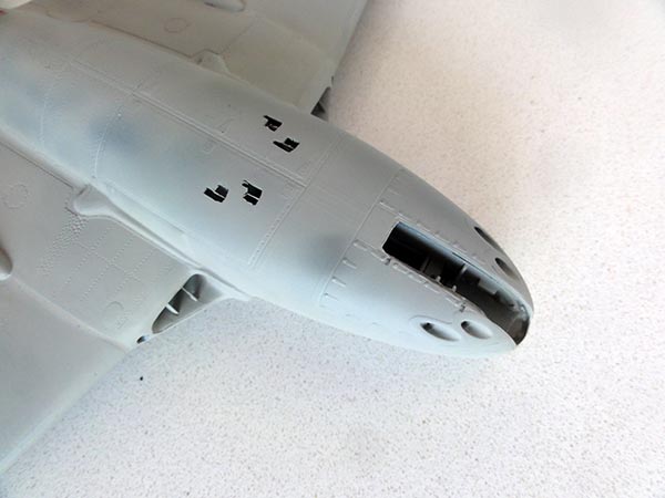
The lower fuselage and nose shell with lower forward canons looked OK as compared to drawings. The canon nozzles were drilled open en a few plastic open tubes were cemented inside.
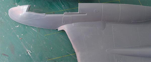
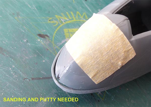
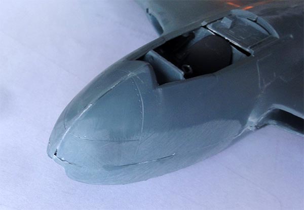
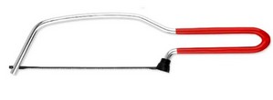
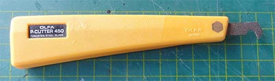
To improve nose shape the forward nose was trimmed by removing 1 mm at the nose tip with a razor saw. It gradually leads to the wind screen area.
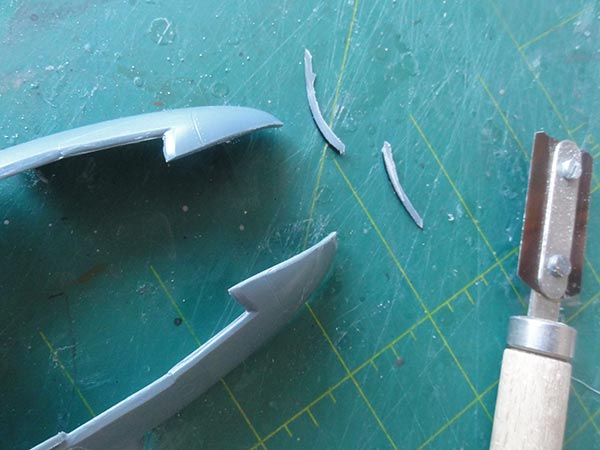
It will improve the upper planform view nose shape.
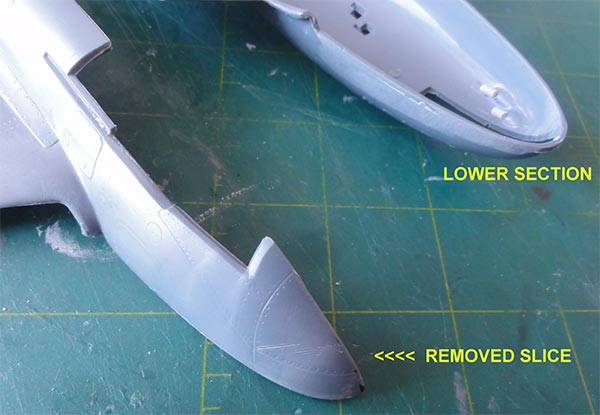
The trimmed upper forward fuselage sections were bended a bit to meet each other. These bended upper nose sections are to be glued later on slightly inside the lower fuselage part top edge. Here it is clear that the corrected nose will be a bit more "less blunt" ...
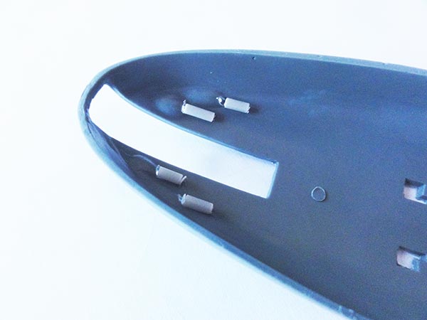
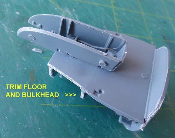
In order to install the cockpit and interior the bulkhead #B6 and floor #F7 in the now narrower corrected nose, at their sides plastic was removed. It need not be exact as nothing is seen.
The wing looks fine and was found to be accurate as discussed earlier.
The wing aileron and dive brake hinge lines were enscribed deeper.
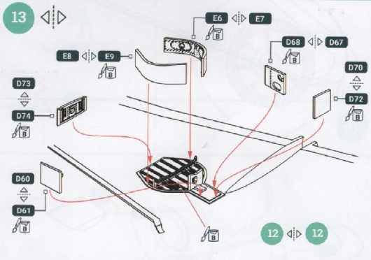
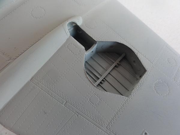
Main landing gear bays have nice structural details. But the raised lugs on parts #D60, D68 for the gear legs are a bit sensitive on their exact installment.
Assembling the upper fuselage-wing in STEP 14 needs care. Plastic strips were used to re-enforce the joint.
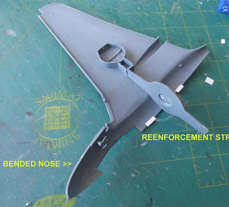
IMPORTANT: the big central bulkhead #E5 with spar ends is crucial for the upper fuselage-wing assembly. The bulkhead fits OK but I set it AFT of the inside ridge.
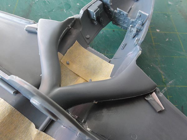
The air flow ducts were used but joined first with parts #E2+E3. I did not use the resin fan part that is not shown in the instructions. (it remains invisible). I set the air flow ducts, after a bit sanding, at the bulkhead. The air duct upper fronts were set with clamps on the upper intake edges and allowed to dry.
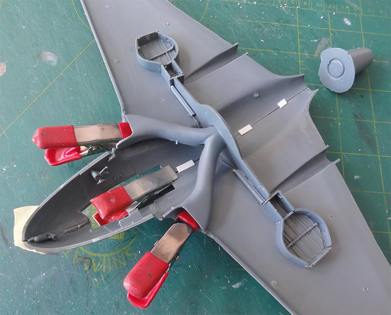
NOTE: the intakes vanes #D8, D9 were NOT yet set as putty and sanding is needed first at the intakes and fuselage. This is one of the weaker issues of this kit.
The lower central fuselage was now prepared.
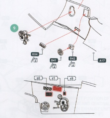
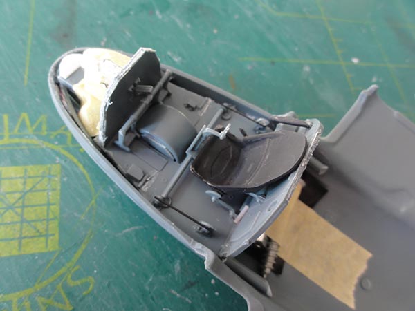
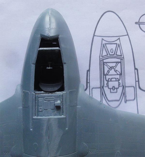
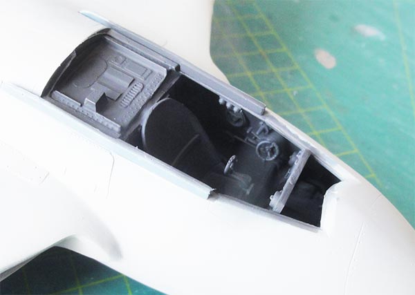
The cockpit interior details were set as per Infinity kit STEPs 1 to 11 and look good. There is a detailed pilots' seat; an ejector seat was not yet installed in these early jets. Do not fit the armour plate #D10 yet, to avoid damage, it can be done later. Between the control wheels #D44, D45 sprue some control wires were set running to the control stick #D17 ends'. On the fuselage sides nice detailed parts are provided in the kit like the elevator trim tab control wheel #D40 and throttle lever in #D13. Other details are cockpit light dimmer panel #D34 and canopy swindle handle #D46. The drop tank jettison lever left of the seat seat adjustment lever are missing but can hardly be seen.
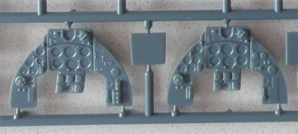
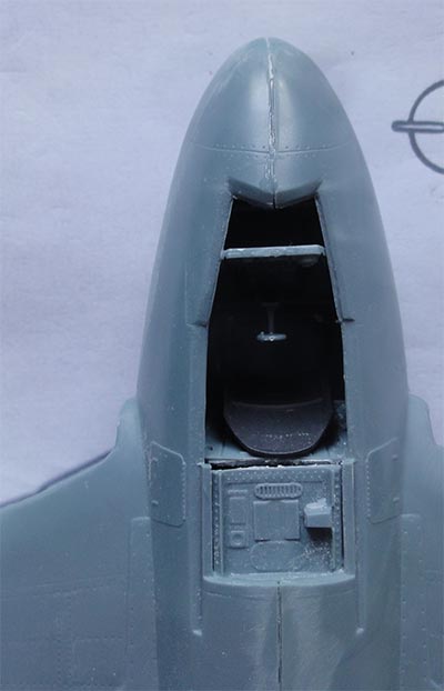
Infinity provides 2 instrument panels with raised details for either the Vampire FB.3 or FB.5 and there are decals for the instrument faces. Though this may seem a bit simplified, it works out fine as the instruments are below a coaming and hardly seen and the cockpit is very dark. (The instrument panel decal was not yet set on the instrument panel).
For the FB.5 panel #D71 was used and it can be set later on in STEP 16 into the upper fuselage.
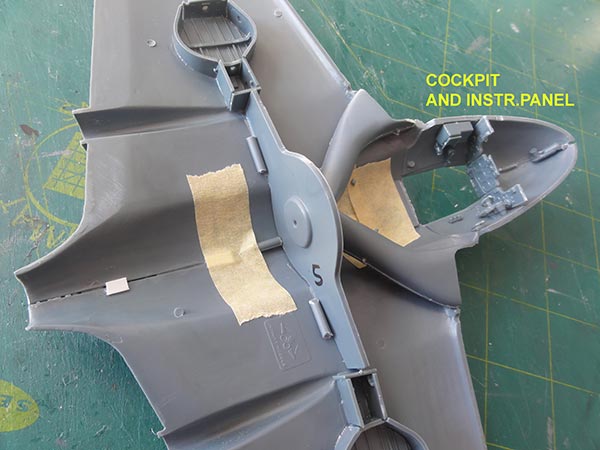
The aft coaming #B8 was set inside the upper fuselage rather than on the cockpit wall. (here some tape is seen sticked onto it...). Small bits of plastic were set behind the opening next to each intake.
The cockpit interior can be airbrushed; but I will do so later on. I added nose weight in the nose to avoid a "tail sitter"; NOTE: later I found that is was invain as it is nearly impossible or it will make the gear collapse. A "pogo stick" will be set later on.
Note the plain pilots' seat. It is seen here in black but later I found it was probably a RPB – Synthetic Resin Bonded Paper – known as ‘the plastic seat’ as in many Spitfires. So it was painted later in various brown shades. The early Vampires had no ejector seat.
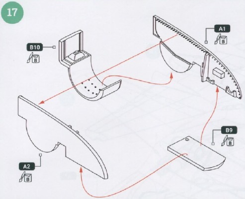
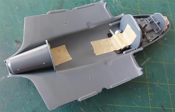
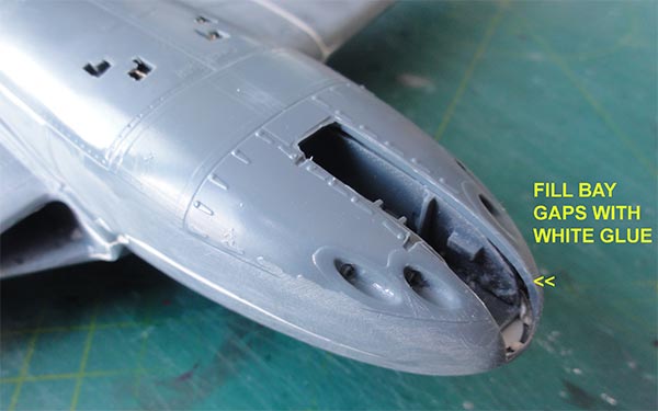
In STEP 17 I needed to trim all the nose gear bay parts #A1, A2, B9, B10, they did not fit into the cockpit floor opening. So the gear bay was made a bit smaller. I also removed a section of part #B9 in order to have it fit in the corrected nose. Note that all internal nose gear bay gaps can be closed up later on with white glue.
In STEP 20 the engine jet exhaust parts were assembled. Not a lot will be seen. I cut away some sections of the bulkhead #B5 to avoid interference with mould pips inside. The small windows #C12, C13 below the jet pipe were also set, it seems these may vary between Vampires.
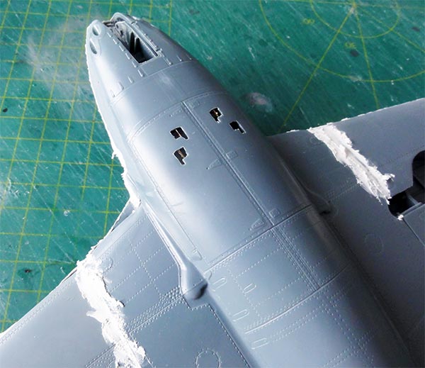
In STEP 15 some tiny etched metal parts #PE23, PE24 for the gun ejector shutes were set with superglue. On their top, a cover was added to avoid "see through" and additional nose weight.
STEP 22: the big assembly was next. Again, do not forget inside the nose tip ballast weight to avoid a tail sitter. Note: there is a wing light opening and part #A7 which is not seen in the instructions may be the light reflector to be set inside.
A lot of assembly clamps were needed and allow all to dry for at least 4 hours. Still when dried there is a tiny spine gap.
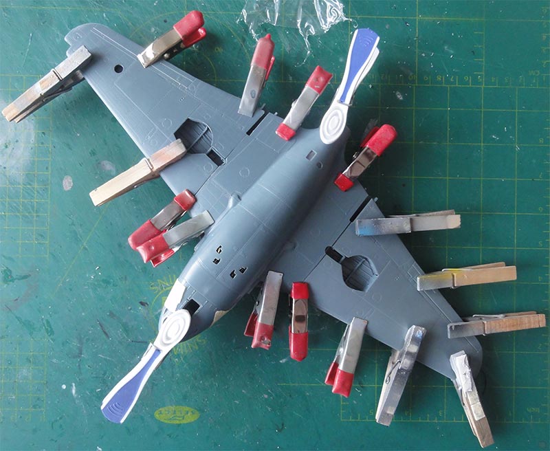
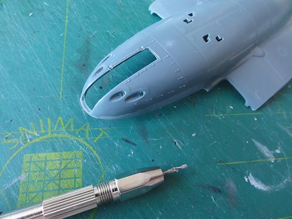
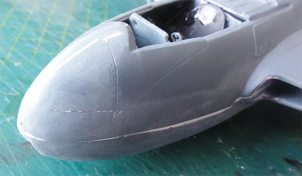
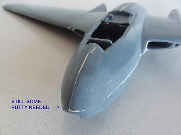
The whole lot needed sanding, notably of the fuselage nose sides to meet the "corrected" nose to get a better looking nose in plan view.
Here a comparison is shown with a planview drawing of the nose....
The plan view shape of the nose looks better.
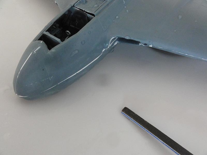
The main assembly was now puttied and when dry sanded.
The intakes need quite some effort to get good, strangely there is a step presumably for the boundary layer flow at the fuselage sides. When sanding had been done, some additional puttying in several passes was again needed.
The sanding results are seen here...
At the nose gear bay, the gaps are to be closed with white glue.

Use a sanding stick for wet sanding inside the intakes.
For the FB.5 the wings were "clipped" as indicated in Infinity STEP 41. This is better done earlier with a razor saw along the panel line.
The transparant wing tip parts #C2, C4 after inside their fronts a bit of red (left) and blue (right) plastic was glued to suggest the bulb of each anti-collision light. The clipped wing tips needed a bit putty and sanding. The wing trailing edges and leading edges needed some putty and sanding as well.
The aileron' edges and dive brake edges were sawed in with a razor saw to suggest movable control surfaces.
A base grey coat was now applied on the main assembly to check for any flaws by airbrushing my favourite Revell Aqua 75 steingrau.
Repairs were made with putty and sanding when needed.
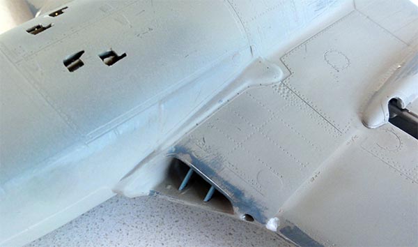
All looked smooth. The 2x2 intakes vanes #D8, D9 were set. I needed to trim these to have them fit inside the intakes in a vertical position.
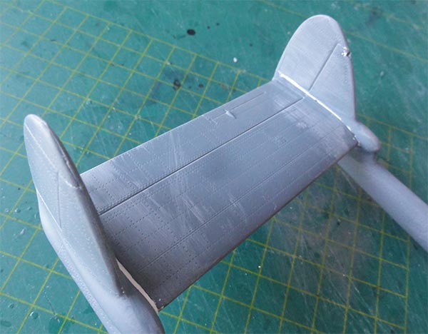
The tail booms and horizontal tail plane were assembled. They needed only some sanding. The elevator hinge line was enscribed deeper and its edges were sawed in with a razor saw to suggest a movable control surface.
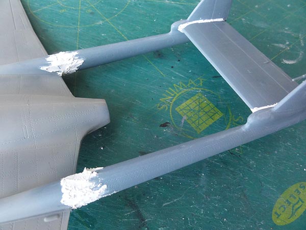
The tail booms and tail plane were set. For added strength, you get plates #A15 to fix the tail booms to the wing fairings. But these needed trimming at their lower fronts to go through the hole. Aligning the tails took some time and measurements. Putty and sanding with sanding sticks was needed as the cross sections are a bit off at the forward wing joints.
Some putty at the mating edges of the stabilizer was also needed.
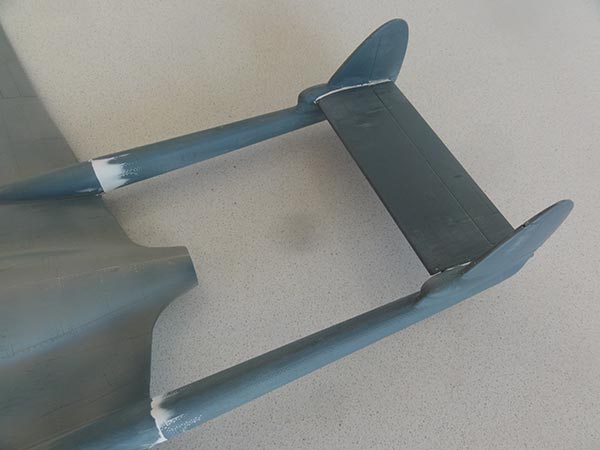
A milestone was reached as sanding had been done and finally some white glue closed up any tiny gaps in the gear bays.
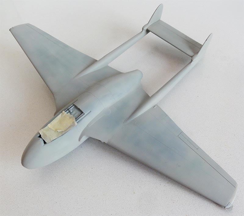
The model was ready to get another base grey coat airbrushed with Revell Aqua 75 steingrau. It looked fine.
Inside the cockpit, a mix of black and white paint was airbrushed through the cockpit opening. The overall inside colour is black but I wanted to avoid a "coal hole". The cockpit details are to be finalised later and the opening was masked off.
Back to 1/32 Models.......
- DH Vampire, "The complete history", David Watkins, Budding books, 1996
...
 .........
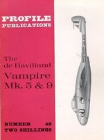
- Profile publications #48, Francis Mason, U.K, 1965
- De Havilland Vampire, W.A. Harrison, Warpaint #27, Hall Park books, U.K.
Web:
https://en.wikipedia.org/wiki/De_Havilland_Vampire
http://www.airvectors.net/avvamp.html
https://www.baesystems.com/en/heritage/de-havilland-vampire
https://dehavilland.co.za/DH100_and_DH115_Vampire.htmlhttps://aerobaticteams.net/en/teams/i122/Telstars.html

(c) Copyright Meindert "designer"/ All rights reserved. Your comments are welcomed by webmaster
Created this page Sept 5, 2022