[ page 2 ]
Sea Venom model in 1/32 scale
... continued from page 1...
page 1
page 2
page 3
page 4 (compl.)
Steps 15-17
and Steps 26-27 and Step 37
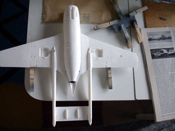
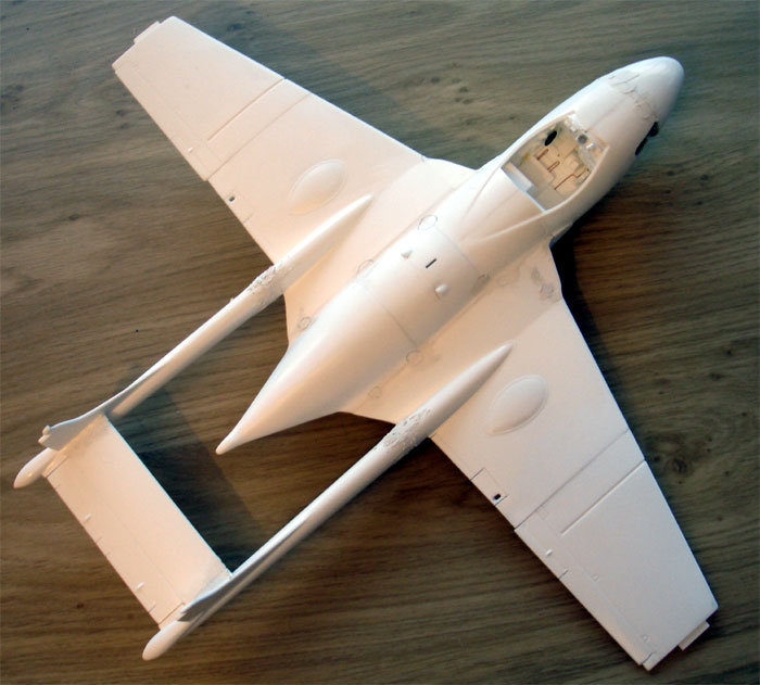
Next, the main assembly continued
with the wings and root sections.
It was decided to close the engine panel with considerable amounts of filler and sanding.
The assembly of the wing roots on the fuselage needed quite some filler and plastic strip as well. At the fine intakes and bay sections, some filler was needed. Step 37 indicates to fit in the wheel bay covers (parts # 21 + 23), do this at this stage.
This also needs "fitting in" oval boom sections inside the opened up flap area; this is to be done with plastic card bended in an oval shape.
![]()
For the RAN Sea Venom model, the
wings would be set not-folded. I first glued the upper halves (11 + 17 and
10 + 16) together to get a perfect flat top surface and later on attached
the lower wing areas.
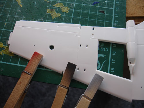
The "airbrakes" in the wings (next
to the tail booms) holes were opened up on both models.
The thin trailing edge flaps are
fitted on the "outsides" of the tail booms and not blended in. You can see
this when looing to pictures. So, on the RAN Sea Venom model, a thin oval
piece of card was glued to both tail booms at the flap area.
Steps 21-24
The tail booms were made as sub-assemblies.
First fill and sand any edges and ridges before fitting to the fuselage.
The pitot was cut off, to be refined later on and do not fit the rudder
parts #32 yet.
Step 25
Careful alignment is now required
mating the tail booms to the fuselage. Some trimming was needed on the
mating glue edges. It gives no further problems however. Leave aside to
dry. Some sanding and filling is needed, but it was not that bad.
Step 50
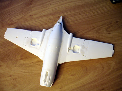
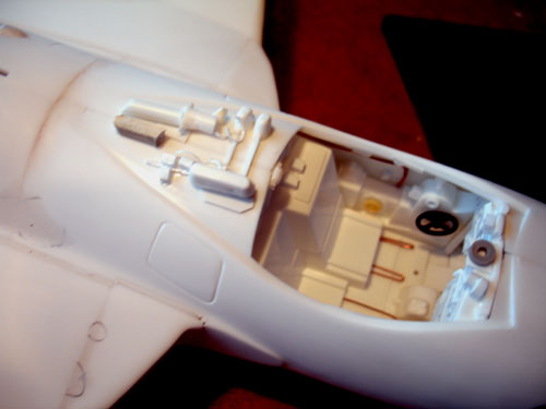
The main wheel bays
need some extra detail from card and closing the edges of them was done
with white glue. Also, the insides of the separated flaps were detailed
on the Aquilon model as seen above.
Immediately aft of the seats, some
boxes were added on the fuselage with wiring. I did not have detail pictures
but used the Air International drawing as a guide.
(seats not yet fitted).
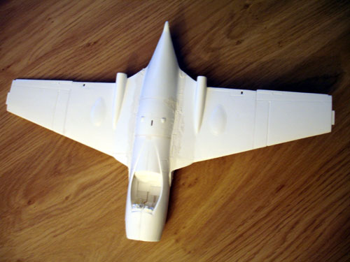
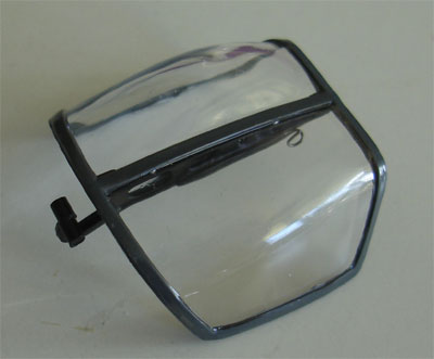
Step 39
Not only the canopy
and glass section, but also the cockpit ridge is provided as transparent
parts strangely enough. The ridge/ lower section part #98 does not fit
very well. It was decided to fit it now.
But first: the inner windshield surfaces of part #98 were masked off with Tamiya tape, as well as the outher surfaces to protect the glass. This would be required as the cockpit still needs painting as well. The tape can be removed later on.
![]()
On to next [ Page 3 ...]
Back to 1/32 models...

(c) Copyright Meindert "designer"/ All rights reserved. Your comments are welcomed by webmaster
Created this page January 27, 2008