1/32 vac / scratch
[ Page 2 ]
1/32 scale vacuform: ID Models (Tigger) SAAB J29 Tunnan
.. continued from page 1....
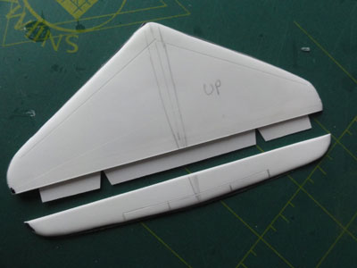
The wing plastic was sanded and cut out earlier. Inside, it required strength, so I added thick pieces of card inside. Make sure the thin airfoil shape is not compromised however. Note that this is a straight leading edge wing, so for an early J29 Tunnan like the J29A.
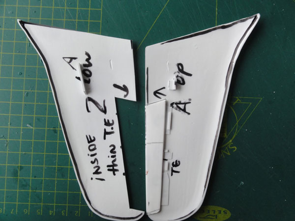
The wing halves got seperated ailerons, this looks beter at large 1/32 scale. The ailerons were separated from each wing part, so 4 parts for the lower and upper and left and right. Make sure to mark the seperate parts in order not to mix them up.
At this stage I also inscribed most of the recessed panellines. This is better done before joining the parts as pressure during scribing is needed. First pencil in where these lines are using the drawings. Next inscribe with a scriber, in this case an Olfa P-cutter using a flexible rod. The trailing edge flap edges were inscribed thicker and also the leading edge outboard slat (for the earlier J29 versions) were inscribed.
The wing halves were now joined.
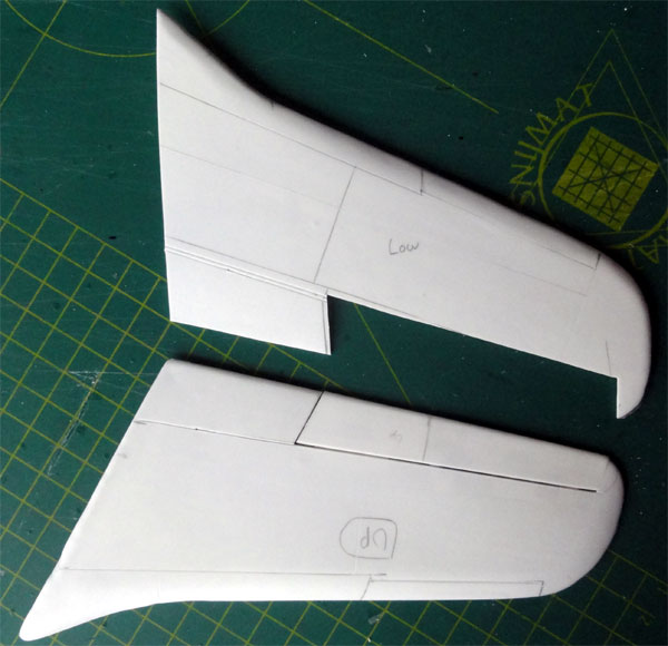
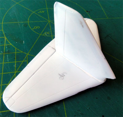
The small vertical tail halves are
seen below here as well and car filler putty applied. Note that mating
surfaces are not yet treated, this will depend also on how these must be
positioned onto the fuselage after has been put together.
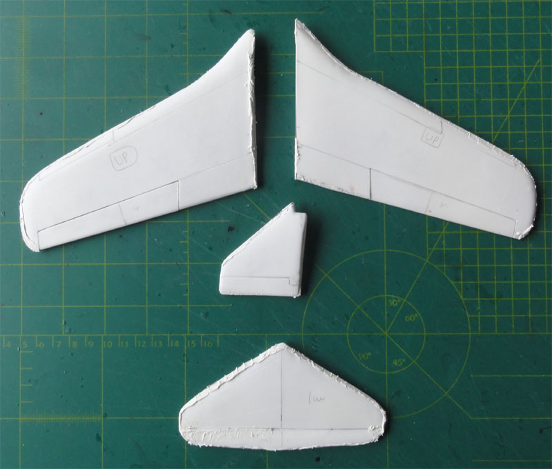
After sanding...
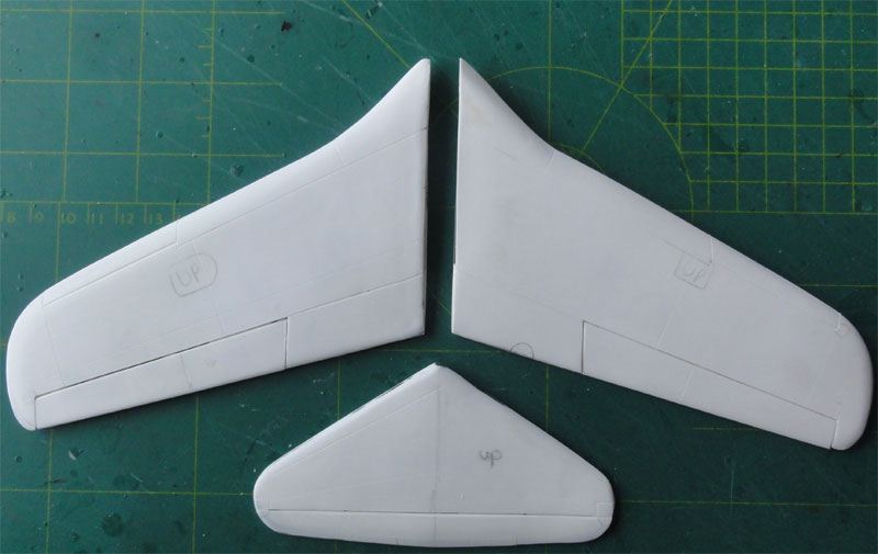
Continueing, I tackled the horizontal
stabilizer. I opted to make the elevator a seperate part, this will look
much better at this larger scale. So the sections were separated and joined.
The elevator was set in place with thin plastic card as connectors, glued
on the upper inner surfaces. The elevator ends have balance tabs and these
were filled. Also the trimtabs were not forgotten as these were inscribed
and their edges "sawed-in" with a razor saw.. Next, still some puttying
was needed. A final round of sanding made the trailing edge even thinner.
![]()
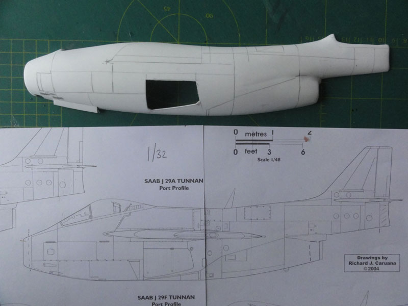
Next, the fuselage panel lines were
marked and the wheel bay and doors. The first panel lines were inscribed,
more will follow later. I feel that only a few rivets to be inscribed later
on as the J29 has at most panels flush rivets as usual for a fast jet.
An early J29A will be made through
this model, but of a bit later production model where the dive brake moved
from the wing to a position forward of the main wheel bays. (the tri-angle
panel drawn on the drawing). This dive brake swivels to the outside but
photos are scarce.
.
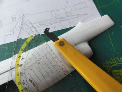
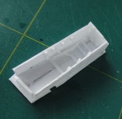
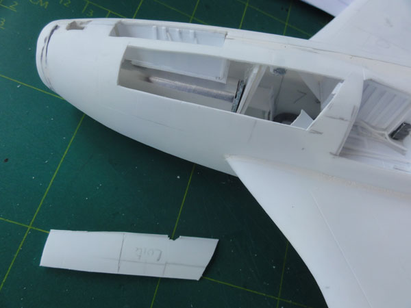
The main doors were cut out, inscribing
first and than deeper with a sharp X-acto knife and the razor saw trying
the retain the cut-out parts like the doors.
 ....
....
The result is very nice indeed.
A nose wheel bay was also made from card.
A lot of internal fuselage details can be added through the various fuselage openings, so the fuselage halves could be joined. Think of undercarriage bay detail, cockpit, jet intake tube and exhaust. So no reason not to proceed further with basic fuselage assembly.
Pieces of sprue were glued on the edges inside the fuselage to get stonger joints and also strips of card were set at places inside. The nose gear bay was installed as well to get a stronger assembly at the nose section at this stage.
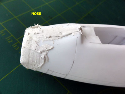
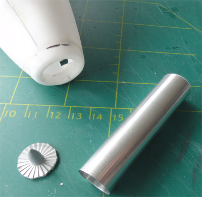
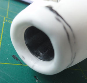
The nose intake ring is very nice as provided in the kit but I could not really check the opening. I estimated the inside diameter to be about 17 mm on the inside before it goes into the duct. I measured it also on a Heller 1/72 J29 kit and that confirmed about this size.
The vacu ring kit part was used to keep the nose section at the appropriate
diameter. Slices of plastic card were needed on top and lower edges to
fill any gaps here. Filling was done. (the lower J29 nose lights recess
was also opened up, not visible here).
 ..
..
Use plenty of fixing tape while the
lot dries. Sanding was done.
.
Filler was now used at various mating
areas. Sanding was done when dried out.
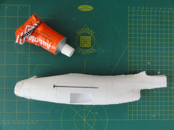
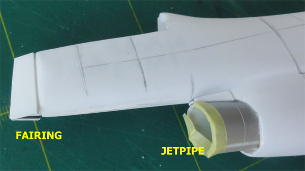
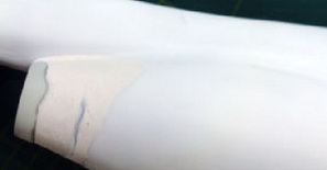
The jet pipe area was now tackled. The kit fuselage lower length is about 6 mm too small but it can be solved here as a tail pipe was installed and filled. I found an appropriate tail pipe in my spares box. (I think it was an F-5E jetpipe in 1/32 scale). Filler and sanding was again needed.
Also, a fairing was set at the rear
to get a tapered sharper rear end. This also corrected the overall length
of the fuselage and it looked much better now.
A.
The wing position was checked again
and drawn using photos and the scale drawing. Some slight adjustment was
needed. Two holes were drilled to get later on two metal spars for the
wing.
.
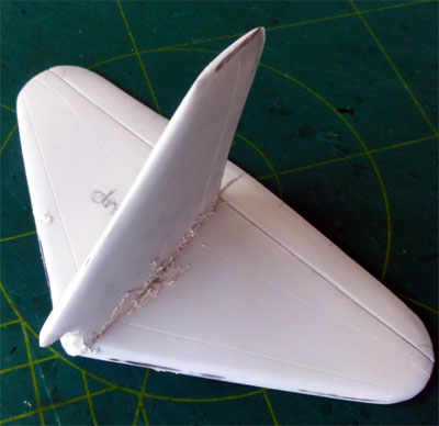
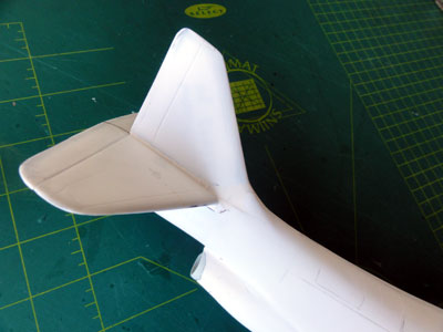
The tail and horizontal stabilizer fitting on the rear fuselage end required careful alignment and a lot of filling and sanding. It was decided to do this at an early stage BEFORE fitting the two wing halves. The wing would interfere while sanding otherwise. So the stabilizer and tail were made now as a sub-assembly.
Filling and sanding was obviously
needed on the vacuform parts.
 ..
..
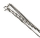
The sub-assembly was positioned at
the fuselage rear. The two metal spars, using purchased metal bicycle
wheel spokes, were set temporarily through the fuselage holes to help
with horizontal alignment.
Quite a big hole was there and a
lot of filling was needed at the rear. It took quite some effort.
![]()
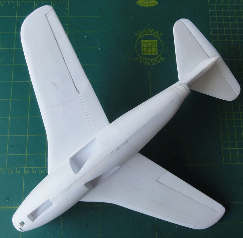
The wing halves could now be installed.
The metal spars were used. Some strips of plastic were used on the spars
to be positioned inside to get a perfect horizontal wing without dihedral.
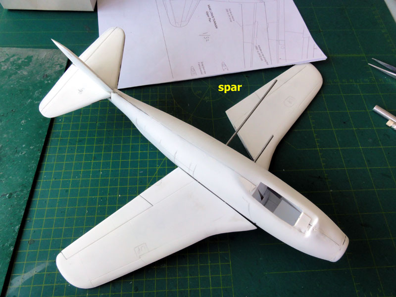
The fit of the wing halves required
minimal filler and sanding, so this was an easy job to do.
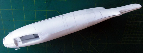
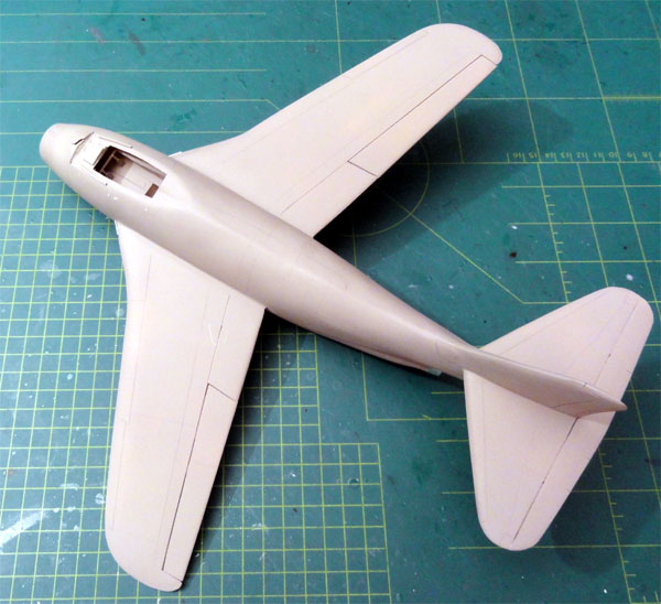
The result is seen here... The J29
TUNNAN is emerging!
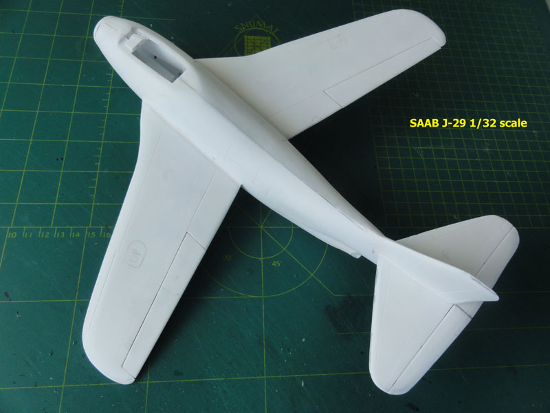
Also the lower
view shows here the opened up nose light recess in front of the nose gear
bay. The model is still basic. w
![]()
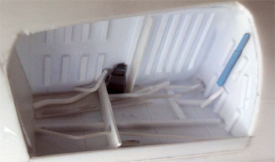
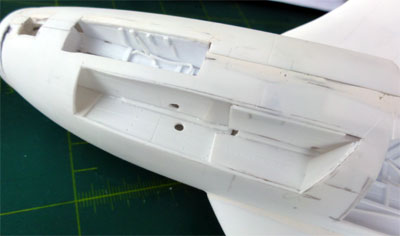
The main gear bays were now detailed
using photos of the real J29 Tunnan using plastic sprue, rod and bits and
pieces. (The main undercarriage gear legs will be made using also metal
rods and fitted later).
![]()
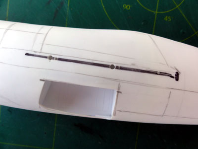
Now, it was time to tackle the nose
intake.
The nose intake has a long tunnel
to the rear to provide air to the jet engine. I first mis-interpreted this
using an incorrect cut-away drawing!! Luckily my modelling friend Peter
had the photos that showed how the intake and its long tube should be!
This was also confirmed by other photos found in the internet (though of
a J29F and J29C). Plenty of photos can be found on the IPMS Nederland Walkaround
and many photos were made by my modelling friend Peter and myself.
See my information SCRAP
PAGE HERE....
For the tube I used thin metal sheet cut from a BBQ dish platter and rolled in shape. It is very thin and thus could be simply inserted through the nose intake ring from the front. First this was done half way. Than from the upper cockpit opening I installed an engine fan from the spares box to get a realistic look. The tube was pushed further to the rear. As the metal is very thin, the "step" at the nose intake is very small and can be filled with white glue.
 ..
..
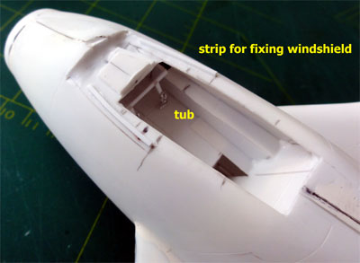
The basic cockpit area was now tackled. A floor was installed onto the intake tunnel and fixed also to the pre-installed bulkheads. In order to check the depth and alignment of the cockpit, first an instrument panel was made. The main instrument panel will be made later on.
Pre-fitting shows that the floor position is correct as there is just enough room and sufficient height for the ejection seat.
The basic cockpit interior is green, for which Gunze Sangyo 320 looks good (to be done later). The instrument details will be made and installed at a later stage.
I also did a check to fit the canopy
and windscreen. Any errors in dimensions should be corrected at this stage
and not later!
The kit canopy is slightly too short
(about 2 mm) in length but that is fine to me. The windscreen and rear
sliding canopy section were separated with sharp scissors and razor saw
after THREE DOUBLE CHECKING! You only got one chance here and an error
is quickly made. So check photos, drawings and so on!
And here the windshield set in place
but not yet fixed.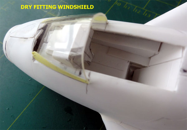 .
.
Strips were fitted to help fixing
the windshield later on. A lot of filling and sanding will be needed later
on, but the shapes are OK.
![]()
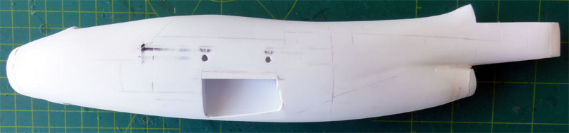
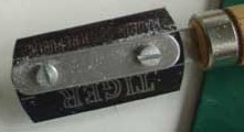
The basic assembly is now fine but
for a large scale kit I always wanted to show some more detail. It was
decided to open up the right side lower gun bay. This was carefully done
with the TIGER razor saw.
.
The bays were boxed-in with card,
details will follow later.
![]()
The overall model was now ready in
it's basic shape. Time to apply a first primer coat through grey paint
with the airbrush. This will reveal any flaws. Essential for a vacuform
kit that would get a vulnerable BARE METAL scheme.
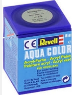
Revell Aqua 75 Steingrau is a great
acrylic water based paint to use as primer. This was airbrushed.
The overall result looks good, but
carefull examination reveals some more filler on the surfaces and carefull
sanding is needed.
So more work to be done!
Back to 1/32 Models.......

(c) Copyright Meindert "designer"/ All rights reserved. Your comments are welcomed by webmaster
Created this page
May 16, 2016