F-4EJ Phantom II
[ page 2 ]
Tamiya F-4EJ model kit in 1/32 scale
JASDF Japan
..... continued from previous page 1....
A step by step approach will be given and depending on the type of work, will not follow the kit steps. The kit step # will be indicated however.
[ Step 0 ] :
Overall preparations
The kit has various "re-inforcement
plates" on many surfaces (note: these are NOT battle damage repare plates!
Phantoms received various structural re-inforcements during their service
careers and also on certain variants, the F-4EJ being no exception).
For the F-4EJ not all plates
should be there and some of them are too pronounced on the kit parts.
Start with the main fuselage part and sand off the plates at the mid fuselage and rear fuselage . Also sand off the plates at intakes parts A1+A2. On the wing tips, the plate at the upper leading edge should be sanded off (so flush) and I suggest to reduce some thickness on the mid hinge re-inforcement plate (parts A4 + A8).
Next....
- First fit the panel A7 as seen
in step 1 and sand flush (as the F-4EJ has indeed no refuelling boom).
- Also fit part A3 as seen in Step
2, fill and sand smooth.
- A small draining hole is missing
on both sides of the fuselage above the root of the wing leading - edge.
Make a hole with a 0.2 mm drill.
- Also, drill two holes in the spine
(suggesting the refuelling indicator lights) in the round panel in front
of part A3 with 0,3 mm.
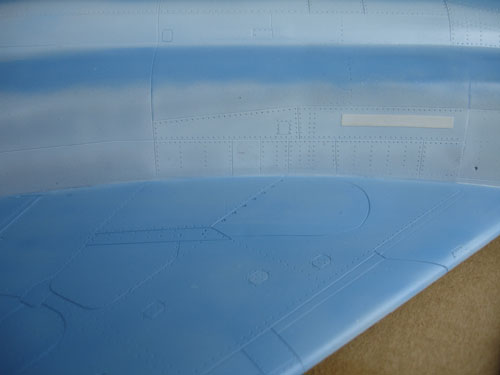
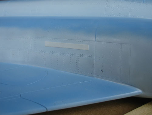
- Fill the RAM air turbine panel
lines with putty on left fuselage in center of walkway (not on the F-4EJ)
as well the corresponding panel on the right side.
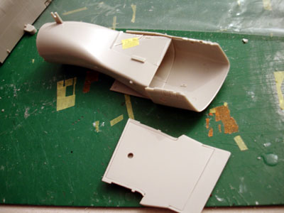
[ Step 1 ]:
Intakes
The intake as provided in the kit
gives problems because when you look inside it, you see edges as the intake
lips do not match the intake tunnels/ducts. You can repair this with some
effort (alternatively buy aftermarket resin "Seamless suckers intakes").
Repair requires some cutting and
sawing but can be done:
a. Separate the two forward intake
ducts as moulded on the main fuselage with a razor saw; use caution and
try to saw in a straight lines.
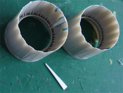
b. Assemble the ducts (parts B26+B42,
B27+B43); do not fit the compressor parts yet.
c. Fit the sawed off plastic ducts
onto the assembled ducts
d. Dry fit the whole assembly and
carefully determine where to fit the outward intakes A1 and A2
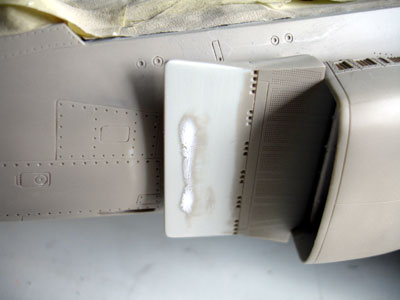
e. Make an assembly as seen below
f. Using Milliput, make the internal
edges invisible. This may take some layers.
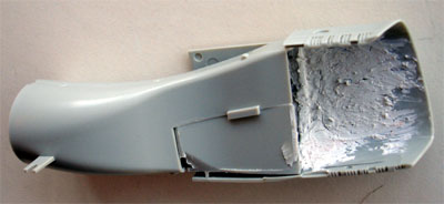
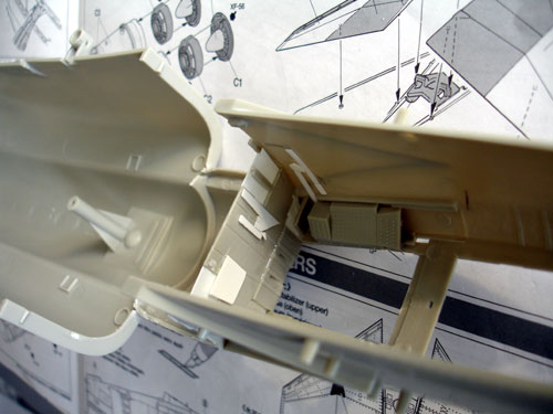
g. Continue with the splitter plates: they have some vents at the lower and upper rear ends. Cut open and add some tiny walls from card. The ramp inboard edge is indeed correctly angled down in the kit. Assemble the splitter plate parts and fill the rear with putty; sand flush after drying.
h. Spray the entire ducts matt white as you are unable to reach them with the airbrush later on. Also spray on white paint at the rear flat panel on the splitter plates.
i. Glue on the splitter plates onto
the prepared intakes and make sure they are well aligned with the main
fuselage.
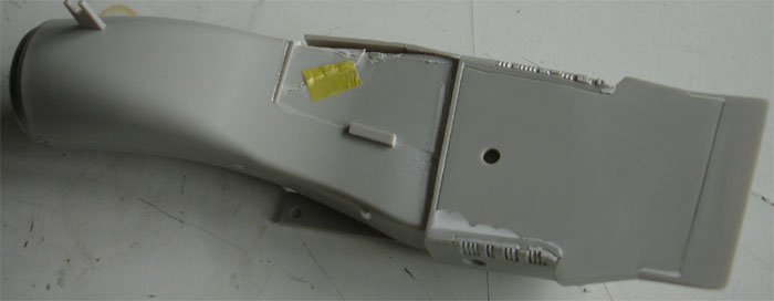
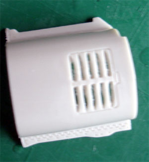
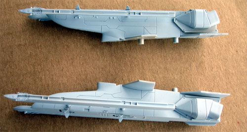
Here you see the whole intake assembly,
being much better now.
![]()
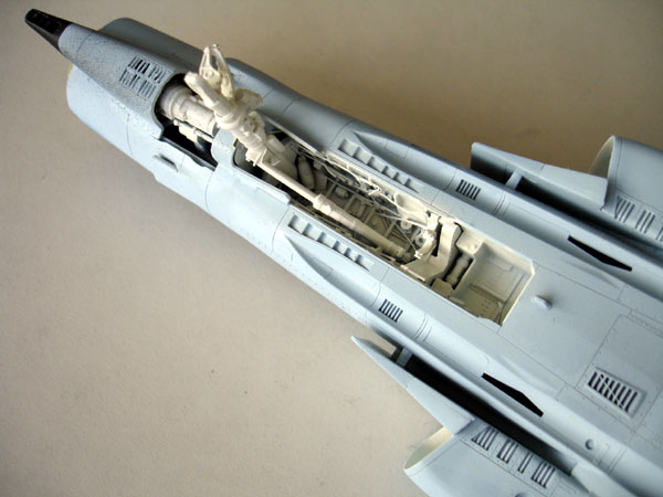
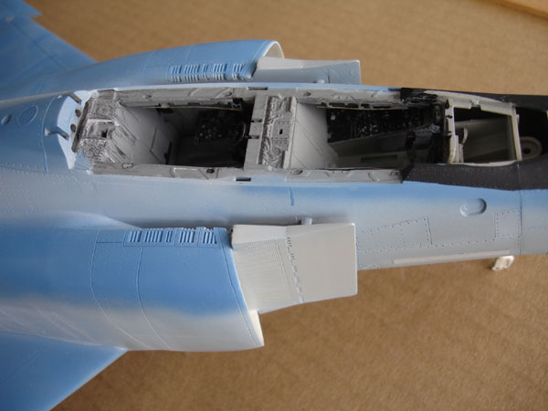
[ Step 2 ]: leave for later, go to...
[ Steps 3- 4
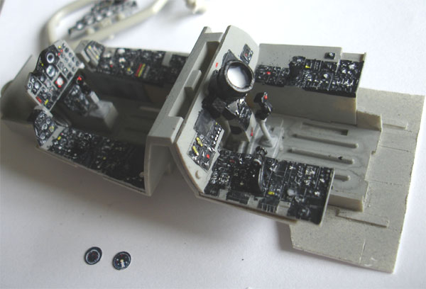
]: Cockpit
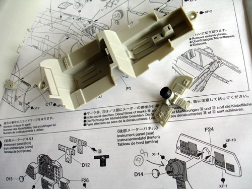
Tamiya provides for the F-4EJ correct
instrument panels (with new parts). The details are raised with knobs and
edges and very good. With some painting you can get fine results. There
are however some small errors in the Tamiya cockpit parts which can easily
be corrected:
a. the scope on part F30 is too small
in diameter. Cut off and replace.
b. the rear bulkhead wall of part
F4 should be vertical and not angled (error in all Tamiya F-4 kits).
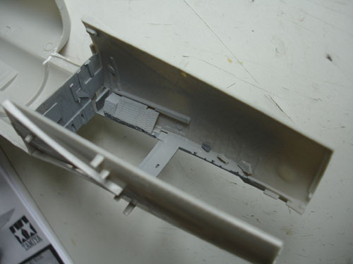
c. the side consoles in the back
cockpit of the F-4E do not go all the way to the back. There are shelves
with equipment to be fitted. So remove some plastic as seen below and add
a floor and new bulkhead. (The top edge of the bulkhead should remain at
the same station position.)
Obviously you can add more details
in the cockpit and for this model Eduard set 32-041
for the F-4E is also used to add
some extra etched metal detailling.
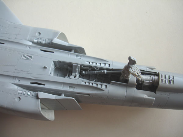
The tub was sprayed light grey. (note:
the missing shelves with equipment will be fitted later on).
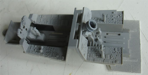
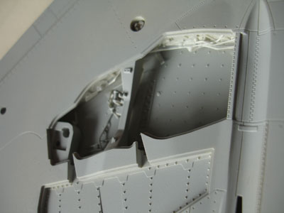
The area at the rear canopy hinge
also cries for some extra details and there is an opening. This was
also drilled open and a horizontal floor inside the spine fitted as seen
below with the tub dry-fitted.
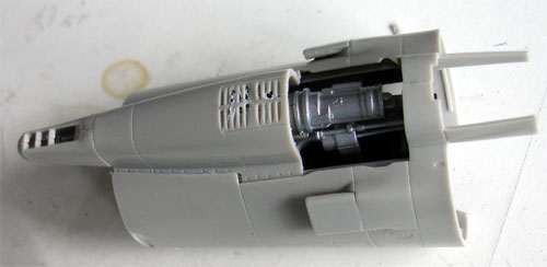
The inner walls of the cockpit got
extra details from card, stretched sprue using also some Eduard metal details.
Below you see also the fuse panel part A10 also fitted.
The canopy hooks fit into lock openings
in the horizontal sides. These were drilled open.
The instrument panels themselves got
the usual treatment with painting with a very fine tip brush, drybrushing,
scratching in the dials and using instrument decals is some areas.
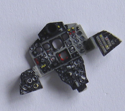
The cockpit also got additional details
painted on and some sprue.
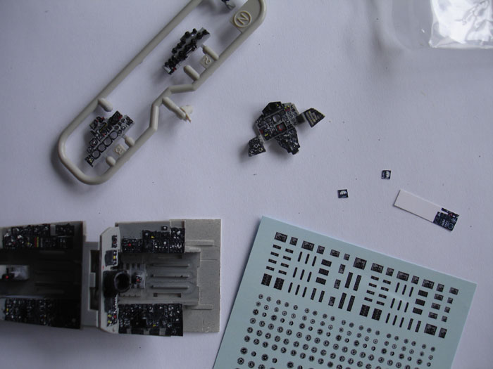
The instrument decals are from an
"unknown" decal source. Add these dials and instruments, using a Waldron
Punch and Dy set to punch them out.
Step 5 was left for later as the cockpit tub would be fitted later
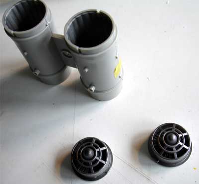
[ Step 6 ]
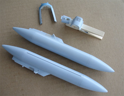
Assemble the exhaust pipes after
spraying them metallic black. The gap between the two halves was filled
with white glue. A final coat of metallic black was sprayed on.
The stabilizer was also assembled,
some minor putty was needed at their tips.
Steps 7 + 8 with the rear fuselage area were skipped for later.
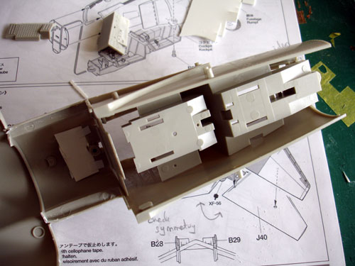
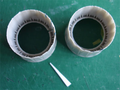
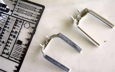
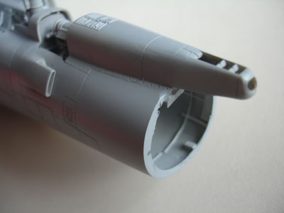
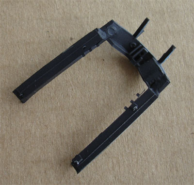
[ Step 9 ]
The Tamiya tail pipes parts #C11 are
too small in diameter at their ends. It was decided to insert a triangle
shaped piece of plastic card as seen below. Simply make an insert cut starting
at the edge but do NOT make a cut at the entire length of the part in order
to keep some strength here. .
Insert the card and glue firmly in
place.
 .
.
Next, the Eduard
set etched metal details for the jet exhaust were added, fortunately you
get some extra parts in order to cover the entire larger exhaust internal
areas with the larger diameter.
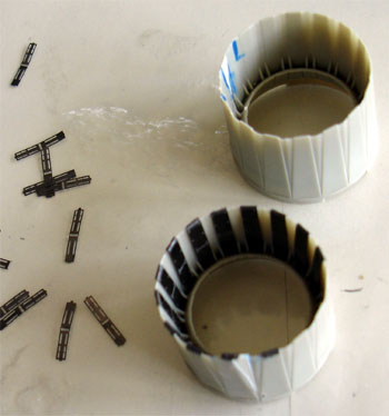
note
the small Eduard parts
The exhaust cone was "loosely fitted"
in place with the metal screws. The tailhook will be added later on.
The small plastic inserts #L6 + #L7
were added (on Tamiya F-4 Naval kits you will get catapult launch hooks).
[ Steps 10 and
11 ]
The wheel bays were OK, and assembled.
Some extra detail was added with stretched sprue in the bays to suggest
hydraulic pipes and tubes.
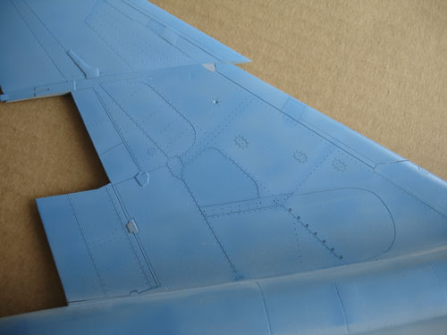
The F-4EJ has no inboard slats,
so the inboard panel lines on parts #A13 + #A14 were filled with putty
(note these are very fine lines).
The auxiliary intake doors on the
lower mid fuselage were OK, the bay was not further "deepened". The overall
result will look OK.
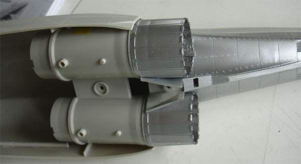
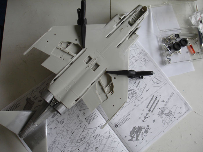
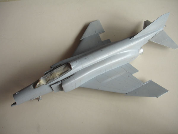
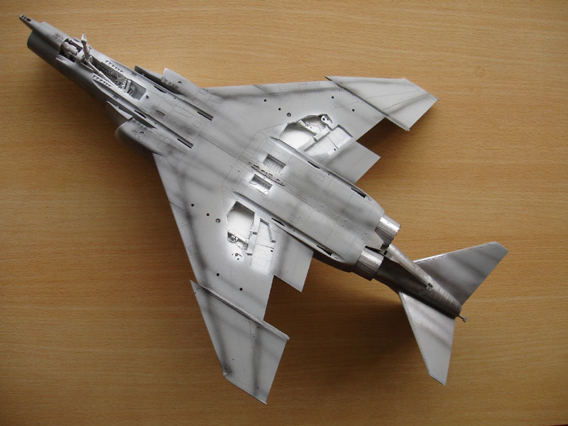
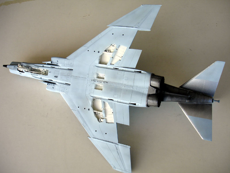
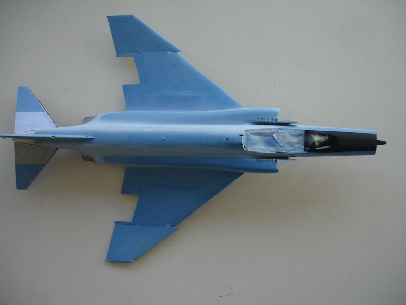
An important next action is....
The overall model parts with its wings were assembled. Take care to make the gap at the wing-fuselage junction as small as possible. For that purpose, a "spacer" made of thick plastic sprue was made and used to keep the fuselage walls are correct distance.
It was also required to fit the horizontal stabilzers, although they are quite vulnerable to handling later on. Also, the "metall" exhaust part from Step 7 was fitted.
![]()
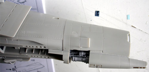
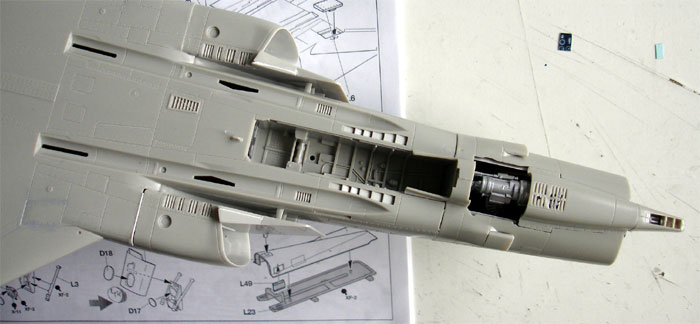
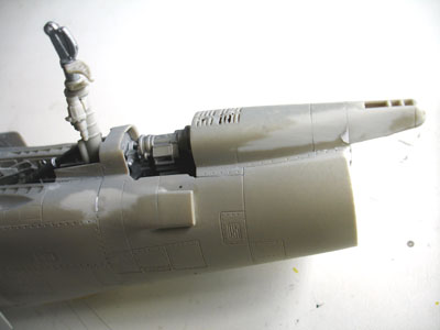
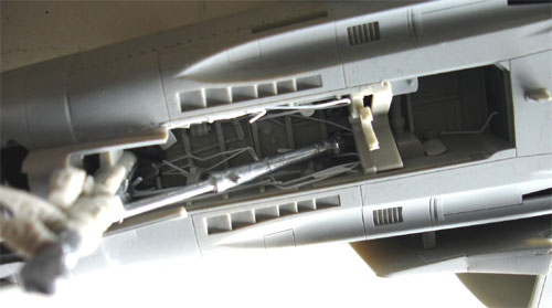
It was decided to show the canon
as provided in the kit. The access panel would be set open. With a razor
saw the lower panel was separated. The canon fairing grills on part were
opened up with an X-acto knife.
[ Steps 12
and 13]
The canon was assembled as shown
and is well detailed. Inside the fuselage some details were added with
rod and sprue. 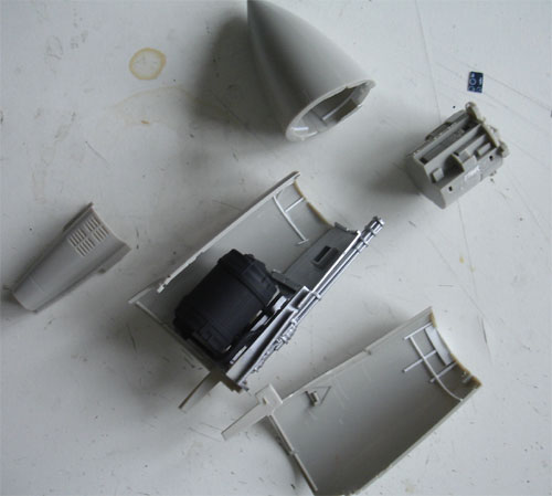
Another view of the canon....
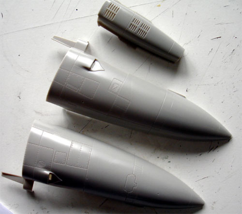
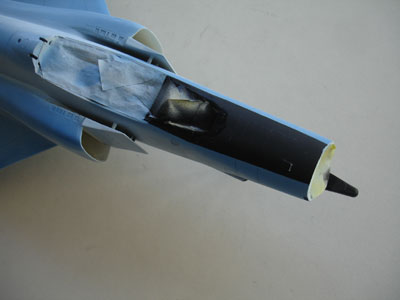
[ Steps 14 and
15 ]
It was also decided to shown the
radarcone open. You get a clear transparant section in the kit and a 'solid"
section. The solid parts were used, and the radar nose cutt off with a
razor saw.
Also, the radar and its equipment
is provided in the kit and well represented. The radar disk #L42 will be
replaced however later on with a part of mesh with opened holes.
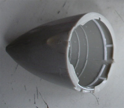
Inside the radar cone, some extra
detail was added with sprue and card.
The view with the canon and separate
radar nose.
[ Steps 16 and
17 ]
The canon nozzle is for the F-4EJ
and correct.
The nose gear leg was assembled as per instructions. You get an metal leg as basis. Some Eduard details were added to the gears. The leg was not yet fixed on the model.
[ Steps 18 and
19 ]
The nose gear and details like the
doors are excellent. The doors will be fitted after the whole assembly
and painting of the model.
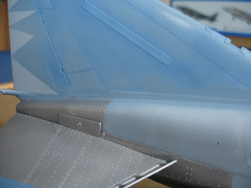
[ Step 28 ] Vertical tail
The vertical tail is OK, but remove a couple of millimeters of plastic at the lip of parts L39+L40, this will improve their fit on top.
Fit the fit onto the fuselage spin and align carefully. The base intake Part L51 could use a little refinement with a sanding stick to make it finer.
The whole model was checked for small gaps and puttied. The cockpit openings were closed with Scotch tape. Adding putty in areas, fill up any gaps and flaws. You can remove putty with nail polish remover without damaging the surfaces as no sanding is needed. Only in areas where you need some "built-up" putty, sanding is appropriate.
After removal
of the putty and polishing the model, it was given a light grey base coat.
This revealed eg. that the intake splitter plates needed some extra filler
as seen below...
 .
.
Also at the gun area some work was
needed.
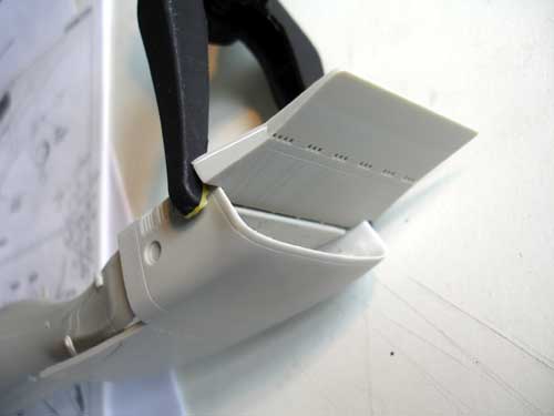
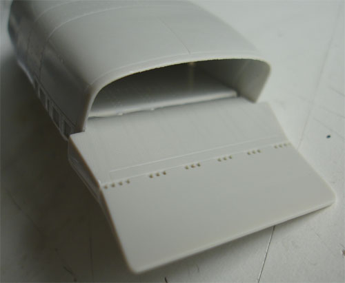
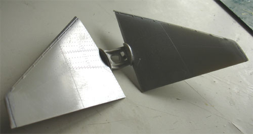
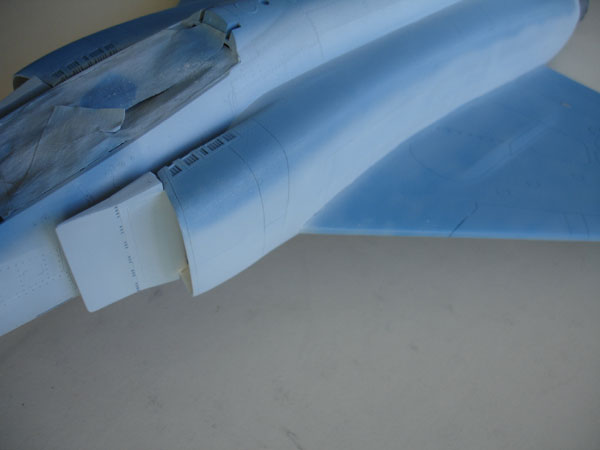
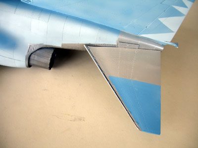
[ Steps 29 +
30 ] Wing tips
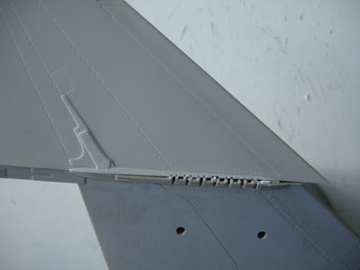
Next the wing tips are to be added.
First, sand off completely the thick "plates" at the leading edges of the
wing tips (parts A4, A8 ) and also reduce the thickness a bit of the plate
at the hinge itself.
Please note that the "tilt angle"
as moulded on the wing tip of the Tamiya kit is much too large! It
should be 13 degrees and not 24 degrees ! This was corrected with the reduced
angle. Some sanding and work is needed to fill up the resulting gap. Also
putty is needed.
 .
.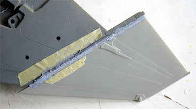
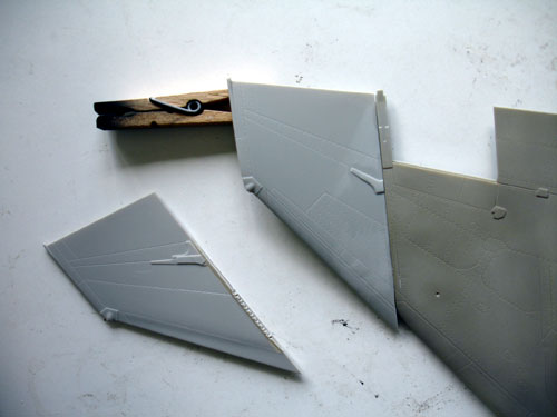
Work in progress on the tips.
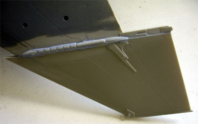
These tip corrections will vastly
improve the look of the F-4 model.
(The trailing edge flaps were not
yet set onto the model).
The main gear legs are not 100% correct, but good enough. The metal legs of the kit will benefit if they get extra details using the Eduard set. The anti-torque rods were replaced etc.
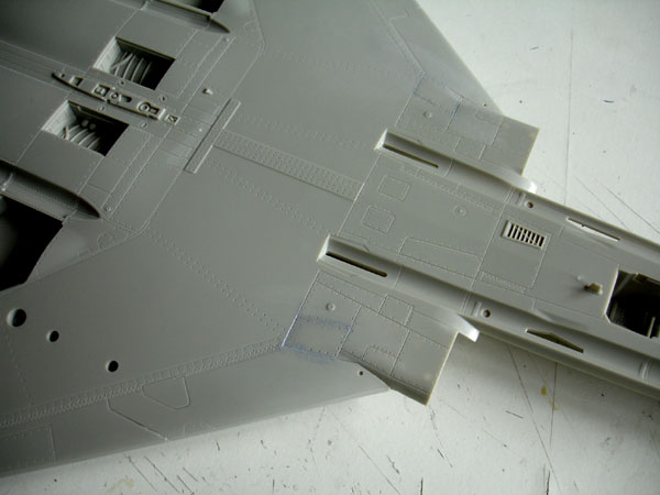
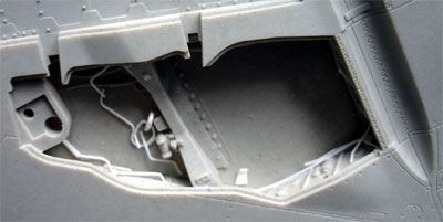
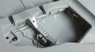
[ Step 21 ] Lower fuselage area
The wheelbays were detailed with sprue and rod as the kit bays are a bit bare.
 .
.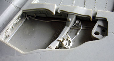
Also, the nose wheel bay on a real F-4 has quite some tubing and wiring! Seen here are the added details. The nose leg was fitted first before adding details.
.
.
 .
.
[ Step 33 ] Canopies
The kit canopy frames would greatly benefit from adding details and the Eduard set comes in handy here. take care when removing the transparant parts from their sprues! Use a fine razor saw.
Note that F-4 has mirrors fitted inside the canopies.
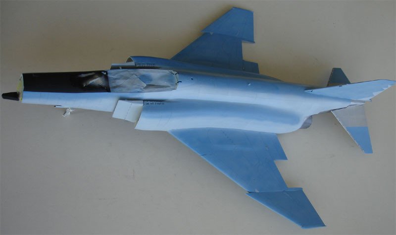
Now, the entire model was given again of light grey coat (Humbrol 127 enamel) with the airbrush to get a smooth surface.
.
 .
. 
This shows that the finish is OK now.
You may be wondering why it took so long to continue with this kit. Well actually it was the choice of colours and scheme for a nice Japanese F-4EJ. I was fascinated by the built of the smaller 1/72 F-4EJ of Fujimi and liked the scheme. This meant I had to make my own decals of this same scheme. I did but at the end I saw some very nice blueish schemes as wel.
I could not figure out what good colours where as Tamiya does only indicate a mix of their own acrylics. I could not find as Fed.Std equivalents, despite some very colourfull Japanese books and searches on Internet. So the built of this model was halted for a few years!
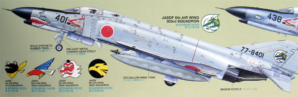
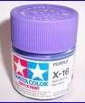
So after some time, looking at the kit decals and all stencilling supplied I decided to go for a scheme as in the kit. Picked was scheme no. E for a JASDF no.305 squadron plane ofJapanese Air Self Defense Force at Hyakuri Air Base.
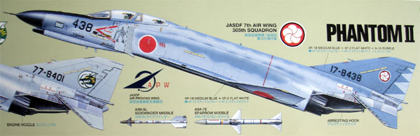
The box-art seen here. You get lots of stencils in the kit, the instructions are seen below....

With the 305 squadron plane paint scheme.. see all my notes on possible colours... I selected the Tamiya mixed colours in the end.
![]()


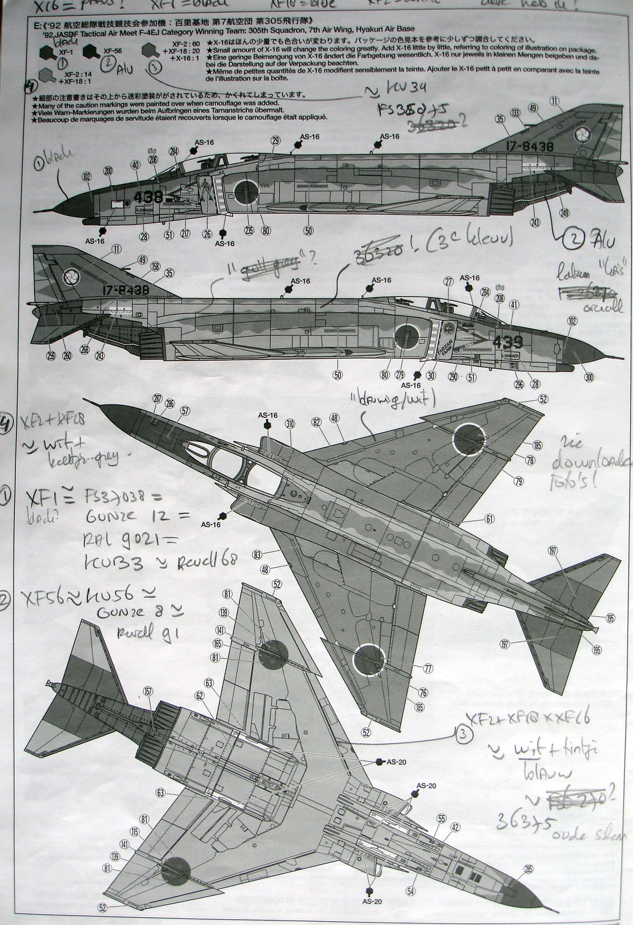
X-16
XF-18
These colours were mixed as on page
22 of the Tamiya kit instructions using these:
TAMIYA XF-18 is a blue colour, XF-2
= white, and X-16 is purple!
Other usual colours are XF-1 black
and XF-56 aluminium.
You will need to thin with Tamiya
thinner as well.
Not an easy task to mix these colours but on the other hand the real planes show large wear with various hues and shines. I came to the conclusion that the lower areas are white with a blue hue and the upper colours have patterns of a darker blue/purple mix.
Make larger paint quantities for re-touching the paint later on, otherwise you are unable to match the colour exactly. Also spray some spare clear decals in these colours for patch work later on if needed.
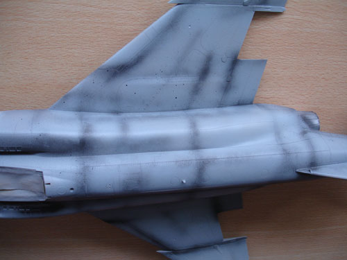
![]()
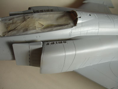
First, a pre-shade
was done with black on panellines and recesses etc. Next, the intakes
were sprayed white. When dry, these were masked of with paper tissue and
tape.
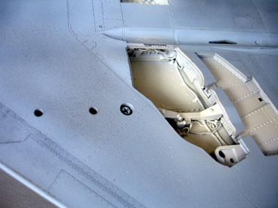
main gear bay with some added details
Starting with the lower surfaces and the upper light colour "white/blue" the model was sprayed with my Steinbeck airbrush, using the largest needle. Do not forget to spray on the low visibility light stickers as well... I forgot and had to do that later.
Than, the darker blue patterns were
sprayed freehand. After drying, I again removed some overspray inaccuracies
with the lighter colour.
Also the anti-glare area at the nose
was sprayed mat black and the metal area at the exhaust and stabilizer
were sprayed metallic, using variuous paints like Gunze 8 metal. (The tri-angle
stickers are not required for this scheme E).
 .
.
.
I than tried to replicate various patterns on panels and panellines with slightly lighter tints of the same colours. This is quite some work but makes the model really interesting as on the real planes various colour differences are seen:
 .
.
this metal area needs some extra shades...
 .
.
Also all the various bits like undercarriage doors, fuel tanks and so one were sprayed as well.
and fuel tanks and pylons
 .
.
and detail of the canopy frame (with
some Eduard details)
with the cockpit masking tape removed
after some years....
Next step is now adding some subtle panel lines details, using Promodeller wash. This will be followed by some gloss coats of Johnson Future and adding the stencils and main decals.
On to next [ page 3 ...]
(c) Copyright "designer"/ All rights reserved. Your comments are welcomed by webmaster
Created this page July 10, 2007