[ Page 2 ]
Grumman A-6A intruder in 1/32 scale kit review & modelling report of the Trumpeter kit
....continued from page 1....
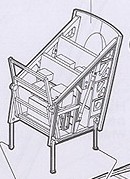
STEP 5
The nice birdcage avionics rack is
in the kit and will be set open. Additional details were added from stretched
sprue, wire etc.
 .
.....
.
.....
 .
.
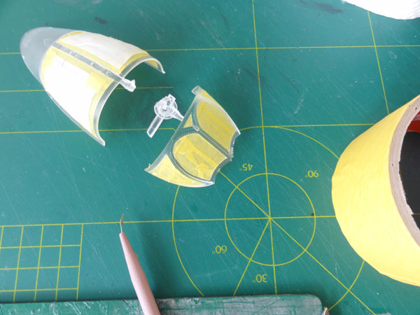
STEPs 8 - 9
The main canopy and windshield are
fine. They were masked with low tack tape and will be airbrushed later
on. PE etched metal mirrors are also in this kit, nicely done.
(STEPs 6-7 and 10 for the undercarriage were discussed on Page 1).
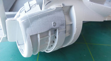
STEPs 11 - 12
One airbrake housing was cut open.
Structural details were added for the "cut away".
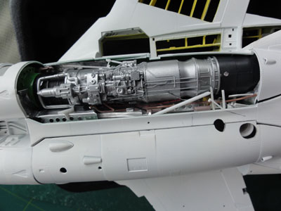
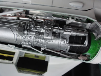
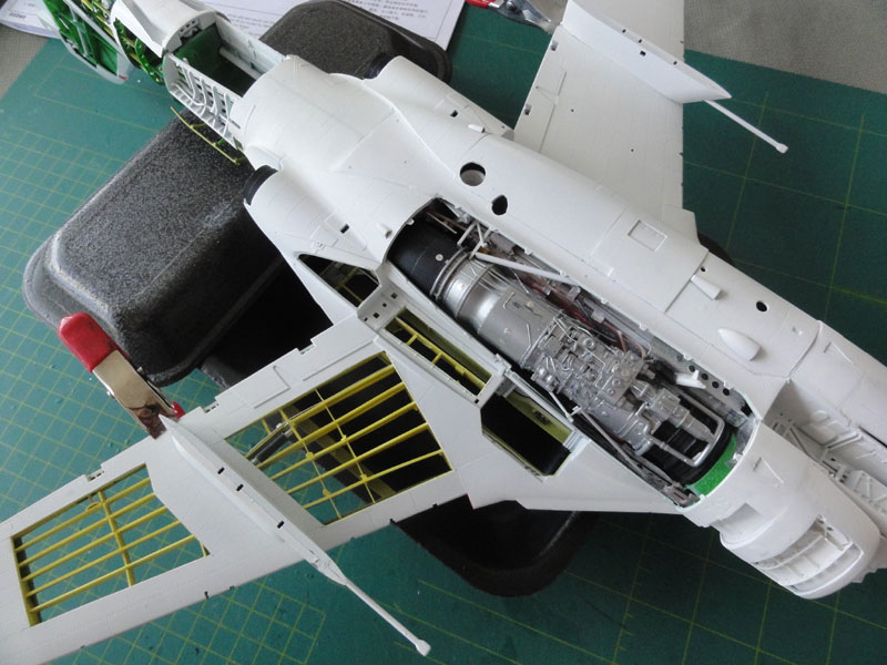
STEP 13
The nose gear was NOT yet set in
place. The major beam and bulkhead is nicely done for the engine bays.
It was not sure of the interior of the engine bay is interior green, so
also some metal aluminium paint was used in places later.
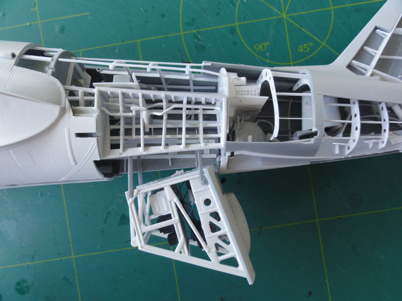
The Left engine bay will be set open
en to be fully detailed later on with rod and sprue. One hatch was also
cut open (part V1 seen in STEP 31).
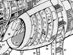
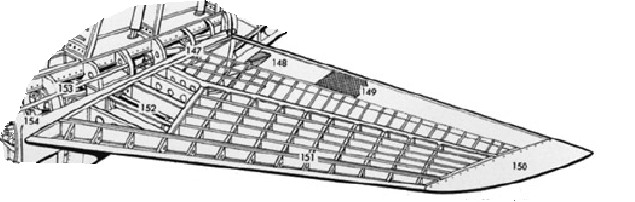
STEPs 14 + 16
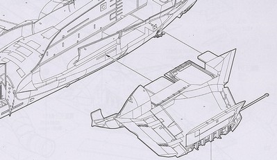
The air intakes require minimal filler
and are inside white. Note that in STEP 3 the intake duct length was a
bit extended by 5 mm in the interior. The left intake was opened up for
the cut away and ribs added with weight saving holes. Some photos and
the cut-away drawing were used for reference.
 .......
and the adapted kit section....
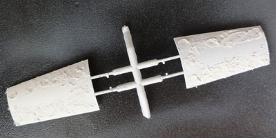
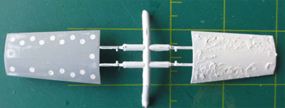
STEPs 15 + 17
Note that fuselage airspeed spoilers
show variations on a real A-6: no holes, some holes or many holes.
David, a former A-6 pilot, explained...
"the
holes in the speed brakes were required on aircraft that had
operational fuselage brakes. The holes reduced the buffeting caused by
the extended brakes. In the early ‘70s almost all A-6s has the fuselage
brakes deactivated. Some squadrons modified the speedbrake plates and
filled the holes in the thought that drag would be reduced but other
squadrons or intermediate repair depots did not. That explains why one
can see such variations in the speedbrakes as seen in old photos".
So check
photos for your particular model. The US NAVY VA-95 A-6A to be made
through this 1/32 model shows NO HOLES. Thin card was glued inside and
all gaps on the kit parts N3 + N4 filled with putty in this case. (I
normally use white car filler putty of ALABASTINE).
 ...
... ALABASTINE car filler

Also the birdcage fit was checked...
but not set in place yet at this stage.
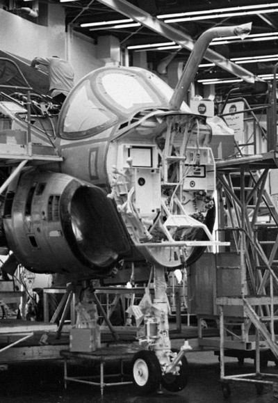
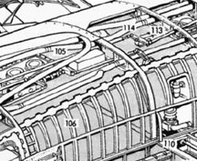
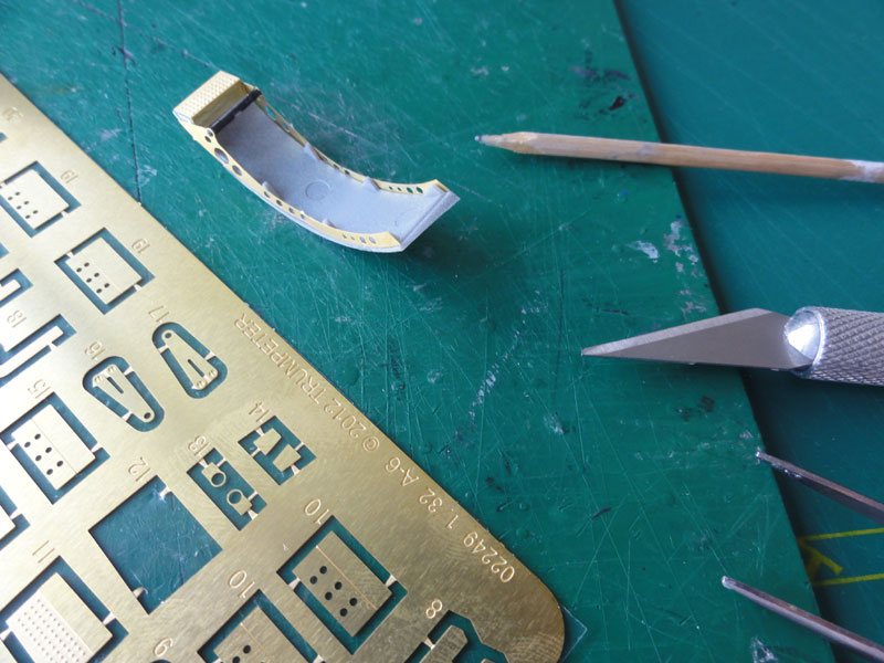
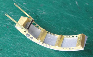
STEP 18
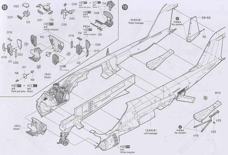
The nose radar details are nicely
done in the kit. The larger A-6A radar is the AN/APQ-88 search- and terrain-
radar and the smaller radar the tracking radar. Only some extra electrical
wiring was added at the back of bulkhead part M2 from stretched sprue as
the nose and some cockpit panels will also be "cut-away".
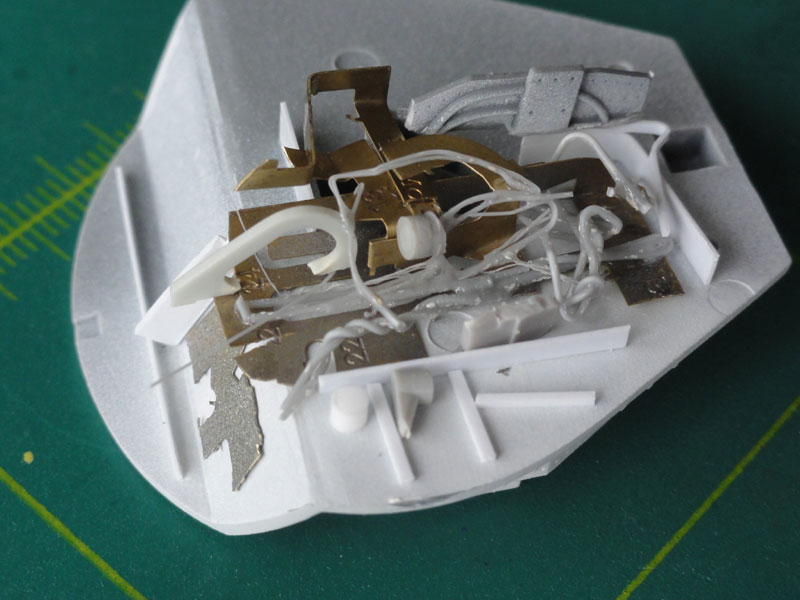 .
.
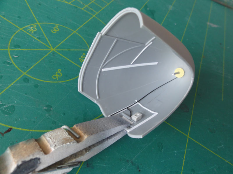
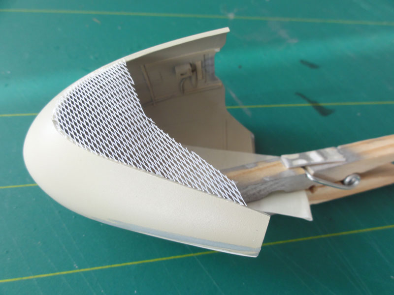
The "honeycomb / fiberglass" nose
structure was "cut-away" and made from some wire from a vegetable net and
airbrushed sand/brown. Inside some detail was added from rod. Nose radome
colours varied on Intruders a lot. Here Revell Aqua 36188
Ocker acrylic was used.
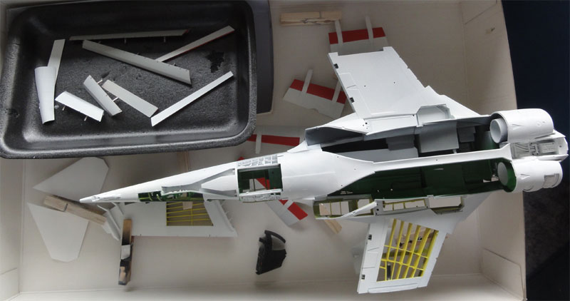
STEP 19
The major assembly was done in some
phases for the fuselage. The tailhook is nicely done in this kit and is
white with black stripes.
NOTE: a nose weight is RECOMMENDED to prevent "tail sitting". Not indicated by Trumpeter!
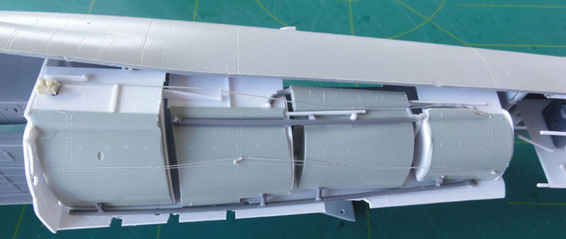
The large central "fuel tanks" inside
the fuselage were made from parts from the spares box and cart.
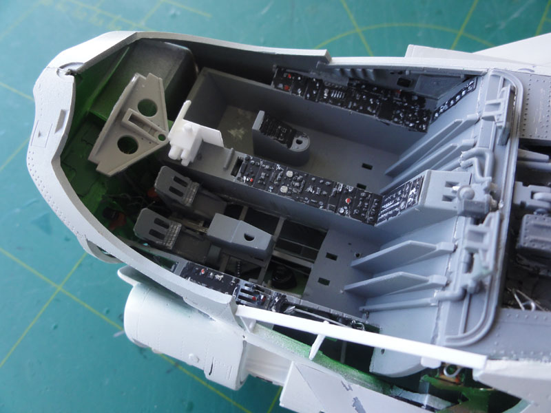
The fuselage halves were joined. Some
of the cockpit interior is seen after added additional detail. Note the
"cut-away" floor.
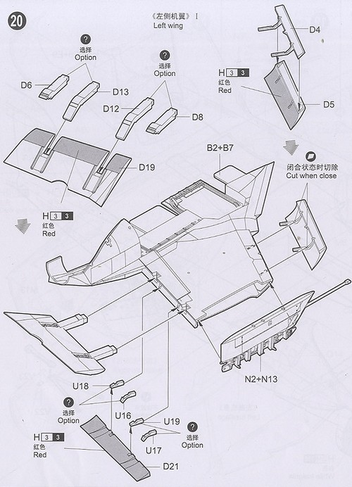
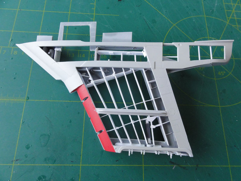
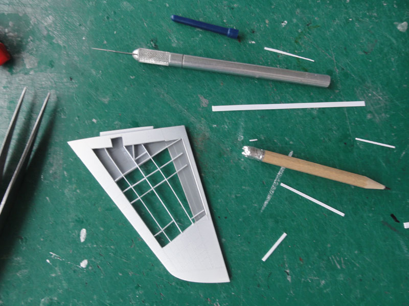
STEPs 20 + 21
The wing is also very nicely done
by Trumpeter with the option to fold the outher wing sections with full
folding mechanism in the kit. For this "cut-away" the wing will be set
unfolded. Also, the flaps can de drooped and slats set extended and the
top wing spoilers are separate parts. The booms extending from the pylons
parts N2+N13 and N1+N6 look OK in length.
 .
.
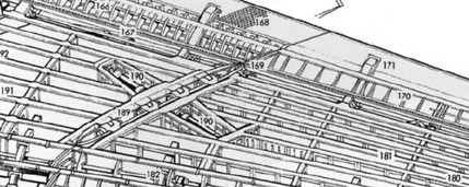
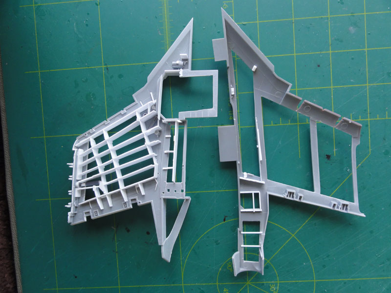
Some LEFT wing halve panels were
already cut-away at an earlier stage. Rib and spar details were added from
plastic rod and card. The folding actuator will also be set in place. All
based on the cut-away drawings used.
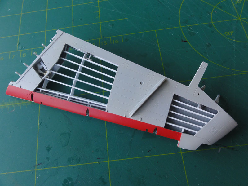
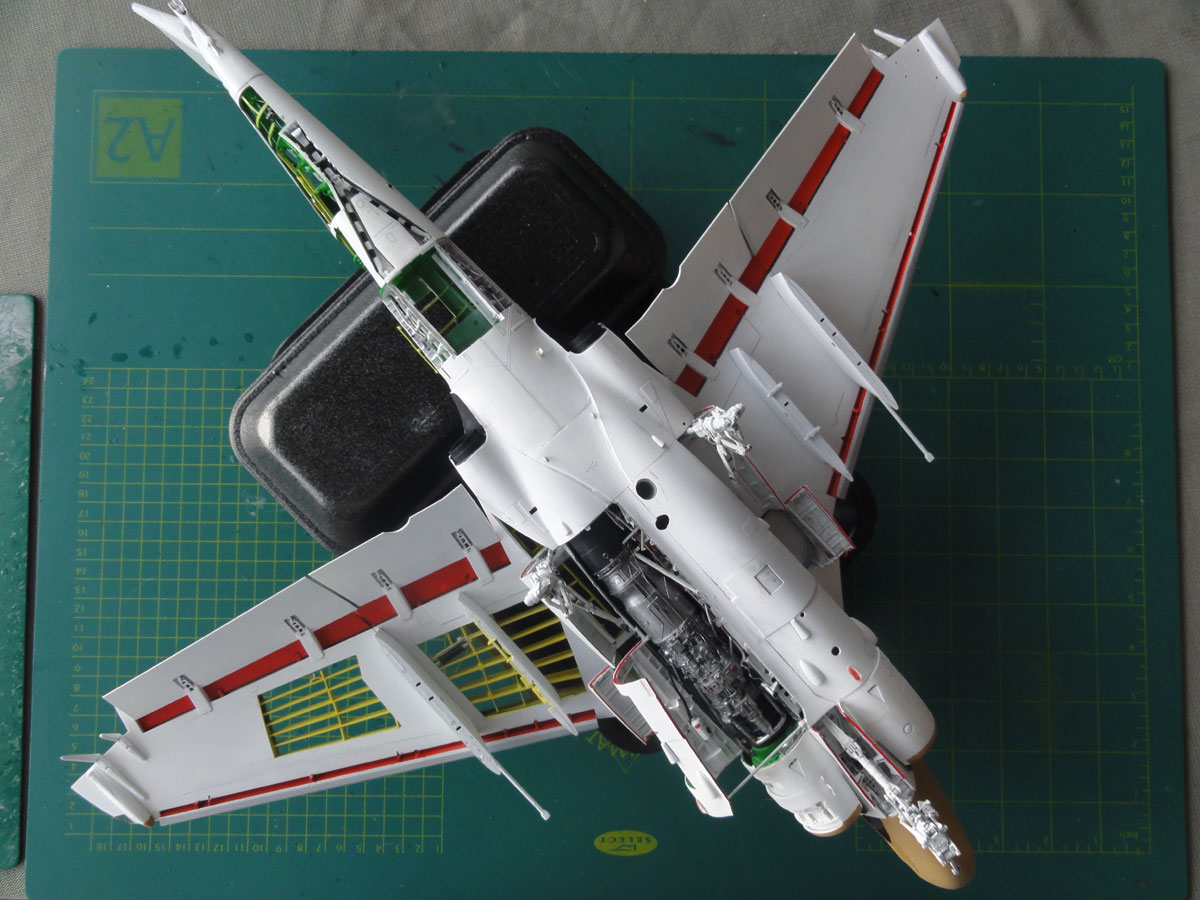
The wing sub-sections were again
airbrushed, work in a step at the time. Lower surfaces are gloss white
(for the old style VA-95 scheme) and upper section FS 36440 gull grey (using
Gunze Sangyo H325). The slat and flap internal areas are RED. Structural
detail still to be airbrushed (yellow) later on.
STEPs 24 - 25
The outher wing panels got a similar
treatment as the central wing panels.
On this A-6A no low visibility lights
were fitted so the engraved panels on the wingtips were filled.
Before installing the wing tip anti-collision
lights, the mating surfaces got a touch up of red (left side) and blue
(right side); (not seen yet here).
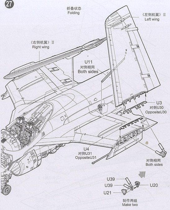
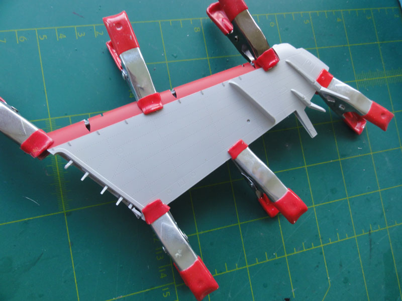
STEPs 26 - 28
The wing was to be set UNFOLDED,
so some additional work was done to strengthen the joints. The kit parts
U2 help here a lot.
 .
.
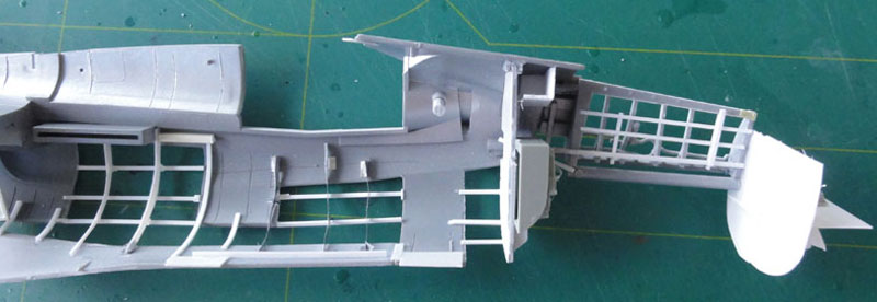
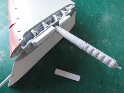
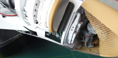
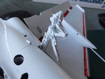
One of the impressive details of this kit is the airflow RAM turbine at the wing root. The A-6A also features a small scoop (Part V6) on the spine, but not on the right cockpit side. I plan to replace the large tail pitot (Part O12) with a thick needle later on.
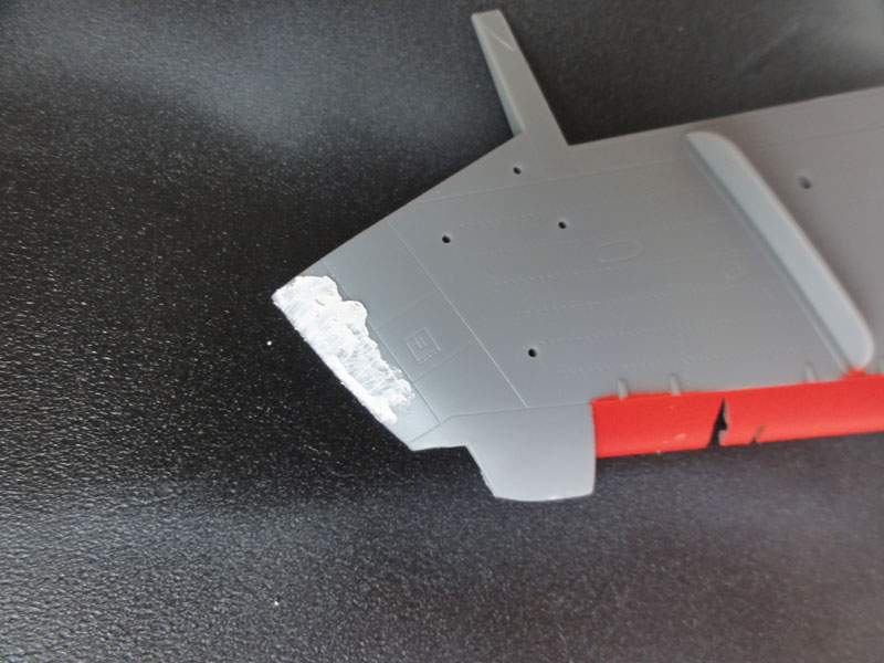
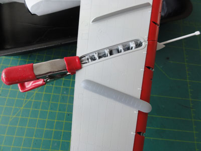
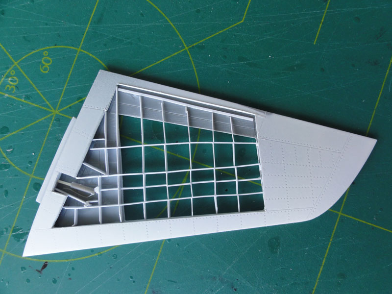
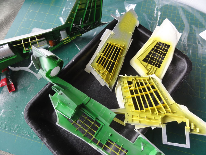
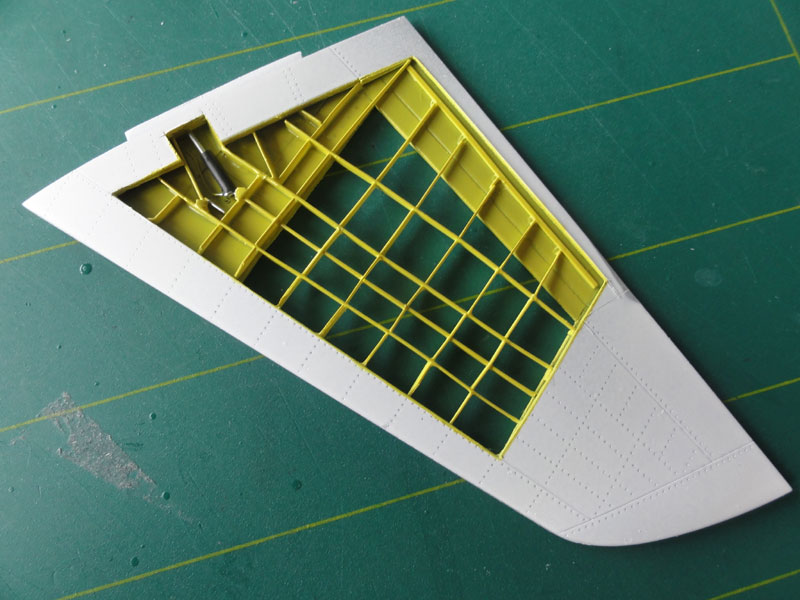
For the left horizontal stabilizer, I cut it open and added structural details according to a cut-away drawing, including ribs and spars.
![]()
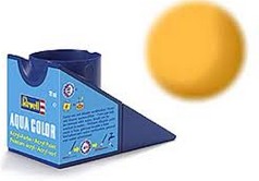
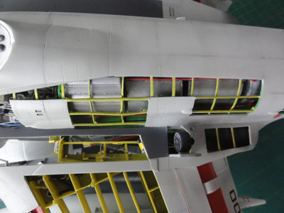
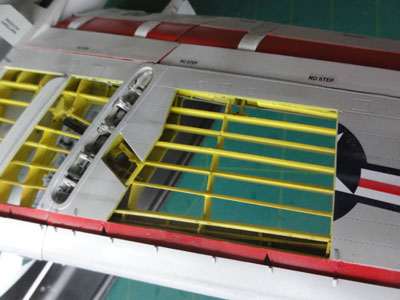
All the structural interiors were
given a yellow colour, but that is a personal choice. Yellow used is from
Revell Aqua 36115. The paint on the structure was airbrushed and
requires a lot of masking with low tack tape. Lots and lots of tidious
work sometimes....
The airbrush was used and it is recommended
to thin the Revell Aqua with its own Aqua Color Mix thinner (so not water).
The other interiors were airbrushed "green", using Revell Aqua 36364. Again a personal choice. All the internal details are NOT weathered as obviously they are inside and never exposed to weather!
The horizontal stabilizer was given
an overall white coat and the leading edge an aluminium edge (not yet seen)
with the airbrush.
Attaching the wing center section to the fuselage works OK but needed a tiny amount of filler for the gaps.
STEP 23
To showcase the interior, I cut away an additional panel (Part V1) in the hatch. (not yet seen below).
 .
.
STEP 29
The glass windshield and sliding
canopy will be set in place later on. The airframe nose is nicely done
as a separate section. The nose - fuselage gaps were filled with white
glue and after drying, will be painted in the appropriate airframe colour.
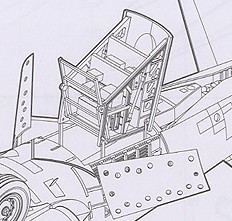
STEPs 30 - 31
Nice are the crew entry steps in
the kit, with some PE parts. The left ladder was set open. Interior is
Red. See also the added cut-away details at the previous
step 14
 ..
..
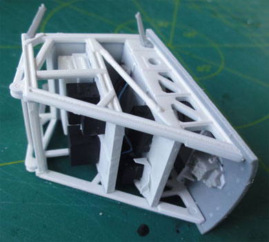
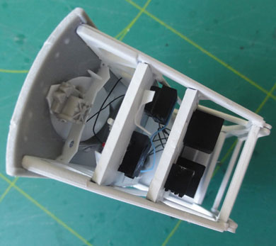
The various bays were detailed inside
as needed. This area is for the "birdcage" should stay clear but has avionics
boxes on the sides and rear.

At the lower fuselage, a gap was still
present between the belly and parts V2 + V4. The gap was closed with white
glue. After drying, paint white. Part V9 is an exhaust with a metallic
sheen (not seen here yet). Parts V8 are also to be fitted.
The model will be set on a display
stand. For that purpose a large gap for the display stand of this "cut-away"
model was made in the belly with also a "locking" hole next to it.
.
The trailing edge flaps slats were
now set in place as indicated in STEP 20. It was easier said than done....
The rails (parts D6, D12, D13, D14,
D15 etc) required quite some cutting/trimming to get them fit in place.
Aligning the flaps and getting them symmetrical takes time and work. The
wing tip speed brakes also needed quite some alignment; in the end the
braces ( U12, U13 etc) were sanded flat at the mating surfaces.
Fitting the combined pylon-wing fold
rib (N2-N13) was not easy and needed some trimming as well.
 .
.
 .
.
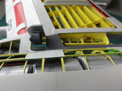
STEP 32
The undercarriage legs, which had
already been nicely prepared, were carefully attached using plenty of
thick super glue ("zapp a gap"). Alignment required making the slots
and gaps slightly larger at the location of the bay ceilings. Once the
legs were secure, the edges of the doors were painted with red sealer
using a hand brush before being installed. One of the doors features a
cut-open panel, as seen in the photo: 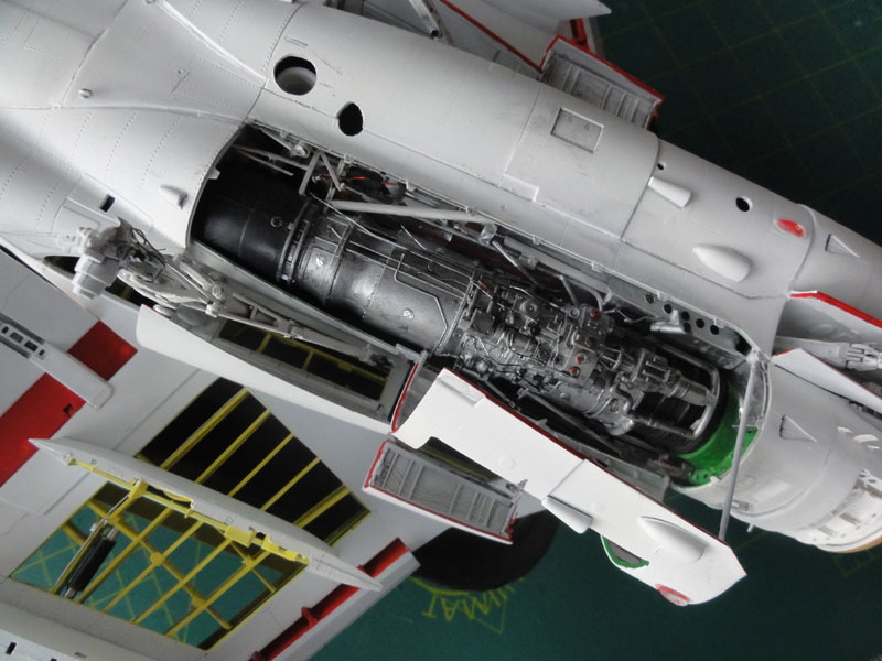
STEP 33
One left pylon was cut "open" to
show the structure and piping. The outboard pylons were set in place.
On to next [ Page 3.... ]

(c) Copyright Meindert "designer"/ All rights reserved. Your comments are welcomed by webmaster
October 28, 2014