Royal Aircraft Factory FE.2b "Early"
[ page 1 ]
FE.2b "Early" model kit in 1/32 scale of WingNut Wings
Modelling report
series
was used during the first world war, mostly as a day and night bomber but also as "a fighter" by the Royal Flying Corps. It was a large aircraft with a gunner seated in front of the pilot in an open tub.
The RAF FE.2b, meaning T"he Royal Aircraft Factory Farman Experimental 2B", was a mild update to the FE.2a that became available later in 1915. It was again powered by a Beardmore, initially the 120 hp version while later F.E.2bs received the 160 hp Beardmore. There were some differences in FE.2b', referred to as "Early" and "Late" mainly in armament and landing gear struts.
![]()
page 1
page 2
page 3
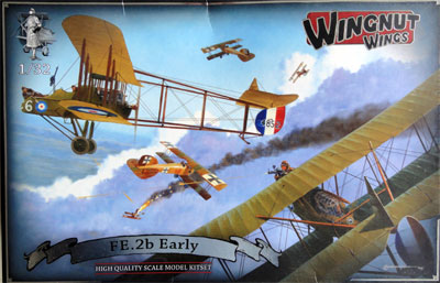
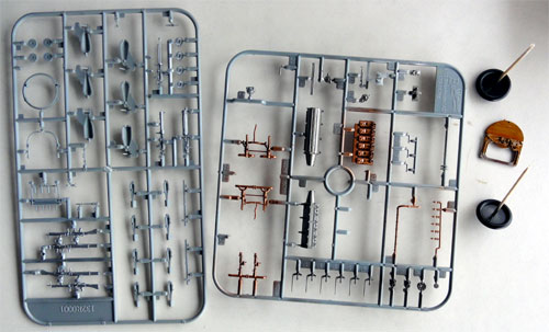
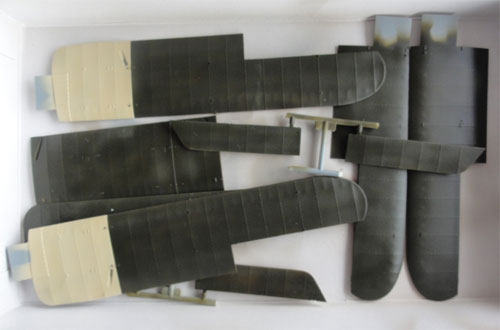
Wingnut Wings issued this kit FE.2b “Early” (no.32014) end of 2011. All parts are very crispy moulded and the box is really full.
 ....
....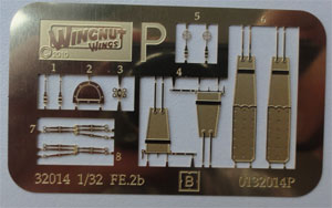
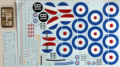
Very nice Cartograph
decals for 5 schemes are provided along with a small etched metal detail
set mostly with belts/straps.
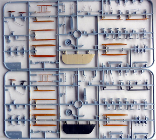
Extra plastic parts allow variations
in gear, guns, bombs and other slight details. The wires are not
in the kit, this has to be sourced by the modeller him/herself.
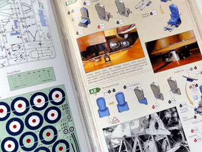
The Wingnut Wings instructions are
a real booklet of no less than 40 pages in full colour and photographs.
It is quite extensive and sometimes a bit confusing, so this kit is not
for the beginner.
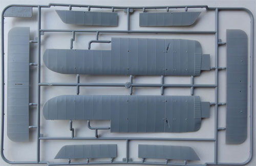
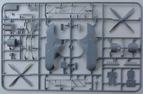
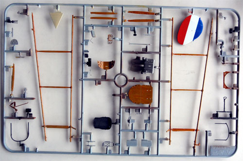
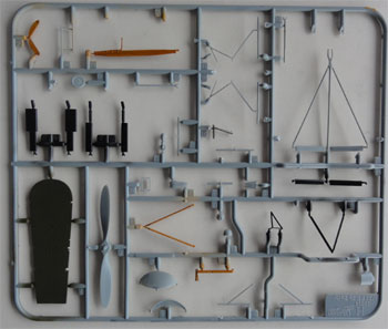
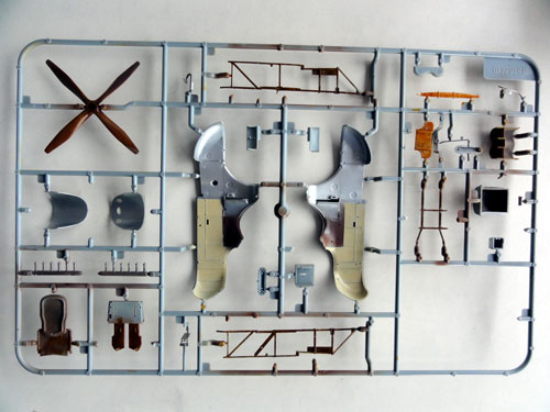
Some view of the parts......
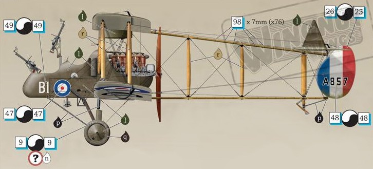
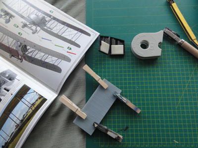
The scheme "E" was choosen for a RFC
22 squadron machine (drawing from and courtesy WingNut Wings):
![]()
Preparations
This kit has lots of wiring! A nightmare
for some, an adventure for other modellers. It was decided that the wires
would be spanned between the struts. The control wires also run over the
entire airframe and are added as well.
They can be fixed in places and corners,
so not a lot of drilling will be required.
Start with....
Separate
the wing sections from their sprues F4, 6, G1, G2, G3, G4. Clean up the
internal moulding "pips" on parts G3 and G4. Joint the upper and lower
central wing section.
 ...
...
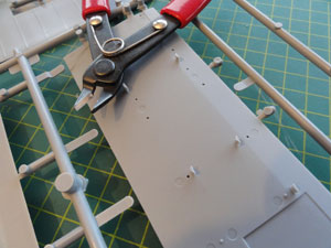
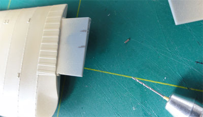
Next, I recommend to strengten up
the joint between the lower wing sections as seen in STEP 10. Small holes
were drilled in the wing lips of wing sections F4, F6 to receive metal
pins to get a stronger joint later on. This is accurate work but worthwhile
to PREVENT breaking up the wings at a later stage while handling the model!
The tail elevator, ailerons and rudder
have control cables. Already drill some holes to rig them with a fine hand
drill in parts as seen in STEP 14 (A46 rudder, and F3, F5, D9, D11. Do
the same for the ailerons F8, F7. )
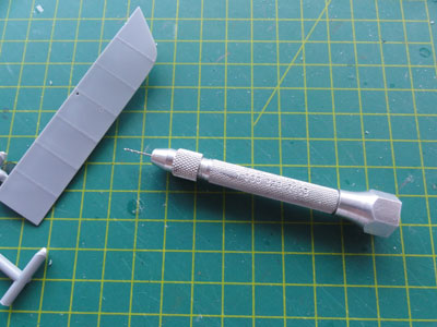
Drill the holes in the wing for the controls and upper wing pulleys A31, A45 as seen in step 14 .
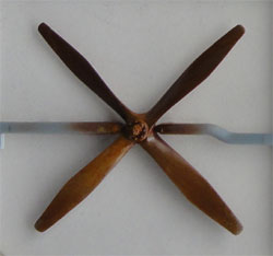
![]()
Painting
Next, what is required is pre-painting
various internal but also external parts. This model can NOT be airbrushed
later on, due to the wires and the many many different colours. parts are
too difficult to reach later on and masked.
So, contrary to usual model builds, painting was to be started with. After deciding what scheme and FE.2b aircraft would be made, the colour instructions were very well studied. For this FE.2b model the scheme "E" of the RFC 22 squadron was choosen.
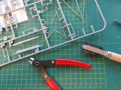
So, individual parts were to be airbrushed/
painted while still in their sprues. This enables handling and painting
to be much easier. Where possible, of most parts their moulding stubs/gates
were removed keeping the limited amount to hold them in their sprues. With
a razorsaw, like the one of TIGER,
saw off the moulding gates and sand off any irregularities.
 ..
..
Some parts were also already assembled
while on their sprues, if this would make a better result when airbrushing.
Once this was done, it was time for
the colour choices.
Many parts have the WWI "PC
10" colour. TAMIYA XF62 acrylic was
used for the PC 10. (if you want a brownish PC10, use Revell 84 enamel
paint). 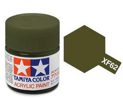
Linnen parts got a coat of Tamiya
XF52 acrylic.
The Harder Steinbeck airbrush was used troughout for the base colours.
Others have the "wood" look.
The wood was applied by:
- first paint the base coat of sand
colour , e.g. a mix of Tamiya XF68 + XF78 acrylics
- when dry, get a tube of dark brown
oil paint (like Talens or Rembrand). Important: it should be oily paint
used by artists.
- dip a small "sponge" or cleaning
stick in the dark brown oild paint, and "drag" strakes in the lenght on
the "sand wood" parts like the wing stuts. This will suggest wood "nerves".
Apply lightly.
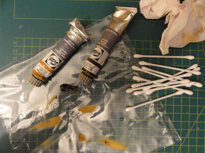
- let dry for at least 72 hours.
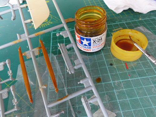
- add a final coat of Tamiya transparant
yellow X24 acrylic.
 ..
..
This will "deepen" the wood look
of the part, giving real wood look effect...
So, some painting is seen...
.
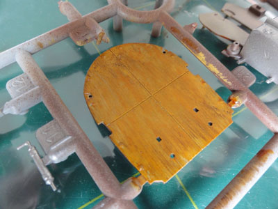
The large wing panels also got their
paint, they were separated from the sprues at this point.
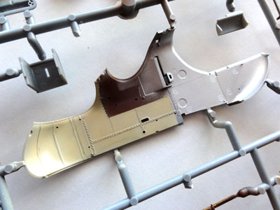
Also, the crew nacelle/fuselage inner
and outher surfaces got the paints. For scheme "E" mostly outside the PC10
colour.
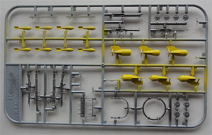
....in close up... and the colourfull
"bombs..."
 ..
..
![]()
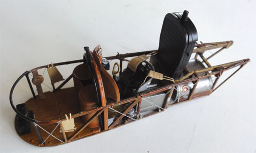
Further Assembly
The parts are finely moulded and
will fit without major problems. In some areas it is even needed to scrape
of the added paint on the glueing surfaces/joints otherwise the paint thickness
will be in the way.
Following the exact numbered steps in the order as suggested by the WingNut Wings instructions is not recommended as some troubles will arise than later on. Here, some suggestions are made for the assembly steps.
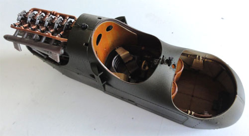
STEPs 1-3
Start with the nice small crew nacelle/fuselage.
Ensure as noted above parts are pre-painted already!
The nacelle is well detailed with
internal struts and pipes. Add the wires, as indicated in STEP 3 (page
9 of instructions) using plain fishing wire 0.1 mm thickness (can be bought
in the... yes... fish accessoiries hobby shop). Alternatively use EZ Line
flexi wire.
Paint the internal nacelle wires
a metal colour at this stage.
Do not forget to first fit part A18
bulkhead to A17 before adding the footplates A21. Also add the compass
A27 or map H4 as desired.
 .
.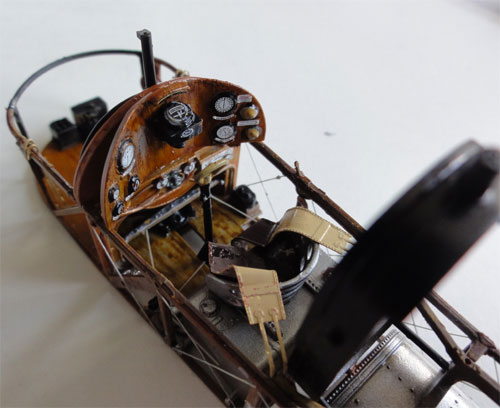
The result is a nice interior straight
from the kit with only added wires and cables.
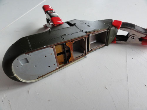
STEP 4
For some schemes, drill a half-circular
hole in fuselage part B13. This is not indicated. It is engraved on this
fuselage half.
STEP 5
The lower plate H8 is to be added
here, but please note to first strengthen the wing sections joints as noted
above.
STEP 6 : gear struts: Leave for a later stage!
STEP 7: leave for a later stage.
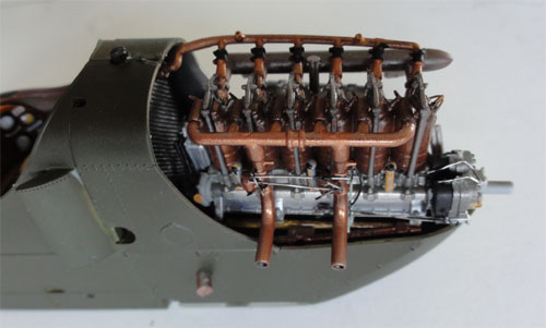
STEP 8
The Beardmore engine is a real eyecather
with lots of detail. I added some additional wiring, like the carburator
control lines. Copper engine details can be painted with Tamiya XF6 copper.
The metal parts can simply be sprayed a metal color, using ALCAD is not
really worthwhile here as the engine will get a greased dirty look. These
engines lost loads of oil!
The rocker arms E15 were a bit too long for a perfect fit, adjust as needed. Also, remove 2 mm from waterpipe part E2.
Indeed, fit at this stage the engine
to the nacelle top as later on the engine is almost unreachable!
STEP 9:
Add the aux intakes A2 and A3 and
the other details as indicated.
Next steps to follow...
![]()
On to next [ Page
2....]
References
- Windsock Datafile 147 - FE.2b by Paul R Hare, Albatros Productions Ltd. U.K.
- Windsock Datafile 018 - RAF FE.2b , by J. M. Bruce.
- the booklet with the Wingnut Wings kit !!!
- the WingNut Wings website with additional info
Back to 1/32 scale Models.......

(c) Copyright Meindert "designer"/ All rights reserved. Your comments are welcomed by webmaster
Created this page
Sept 20, 2013