[ page 2 ]
1/32 scale model of Kitty Hawk OV-10 Bronco modelling report
... continued from page 1...

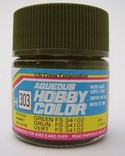
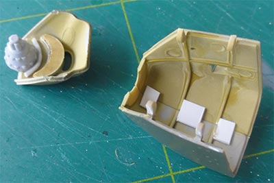
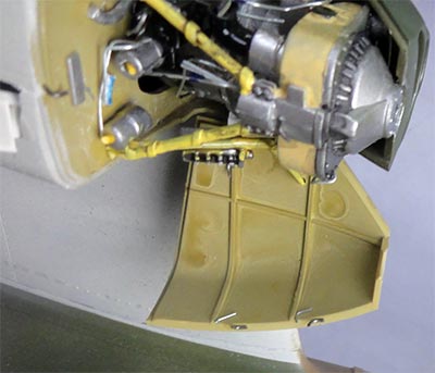
The main inside bays, cockpit and engine bulkheads were airbrushed. White on the inside gear bays, grey 36251 at the cockpit tub and chromate yellow at the bulkheads. Also the gear legs that were detailed a bit as seen previously got a light grey colour with the airbrush. The guns inside the stubs/ fairings were also set in place.
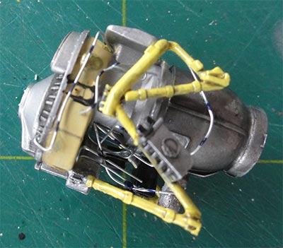
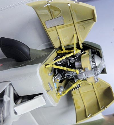
Two engine assemblies were also airbrushed and each engine frame was painted yellow. The engines also got additional hydraulics and wiring.
This was all set to dry.
STEP 23
The propellers were now tackled. I used a small drawing with lines at 360/3 = 120 degrees to align the separate blades. Note that Kitty Hawk gives you 2 types of blades, I used for the OV-10E (= OV-10A) parts F45,F46,F47.
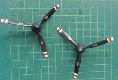
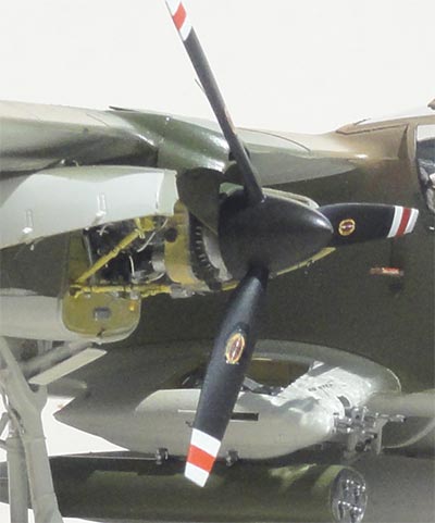
The props were given a black base coat. The propeller tip white-red-white stripes were masked though decals are provided as well. The tip colours were airbrushed. (I did not see anti-icing metallic leading edges so these were not added).
The instructions also let you install a fairing #H33 below the tail boom; I did not see it but saw 2 antenna fairings #H33 in stead on the top of the boom; may be this varies between Broncos.
Also other antennas may vary.
STEP 26
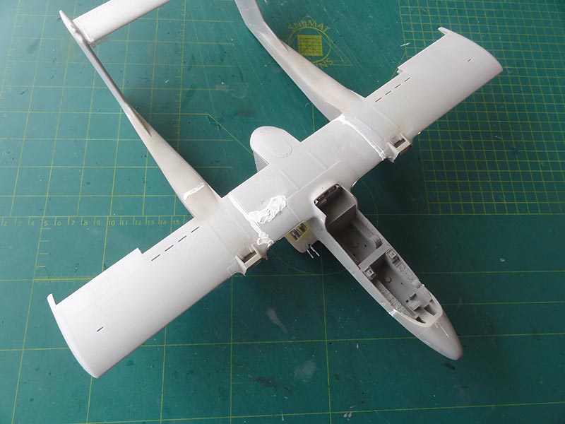
The outboard wing sections and tail booms were joined with the fuselage. As explained, for added strength a spar was installed.
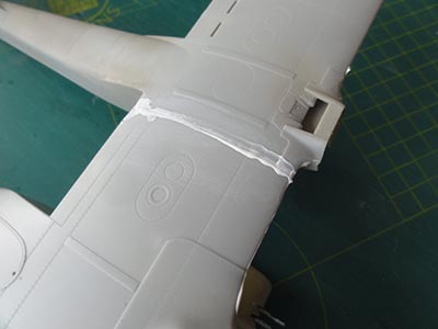
Some putty was needed followed by sanding.
I also had a sink mark due to the glue at the upper right joint. This needed more putty and sanding.
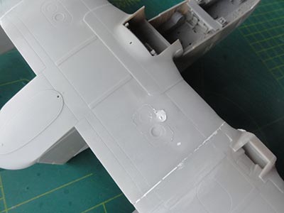
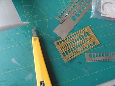
Panel lines and panels were inscribed had been disappeared a bit after sanding. This was done with a scriber and template, particularly at the upper wing areas.
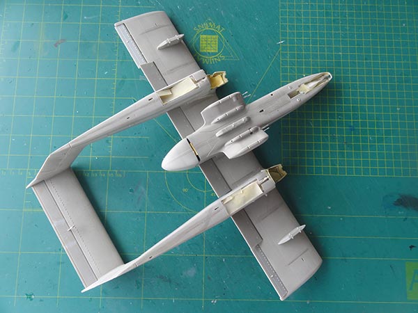
The major parts are now basically joined.
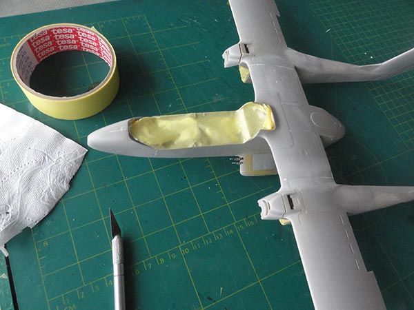
The insides of gear bays and engine bulkheads already had a base white colour and chromate yellow. These areas were masked off.
I airbrushed the model overall a base grey coat with Revell aqua steingrau #75 to check for any gaps and irregularities. It turned out a bit more sanding was needed at some places.
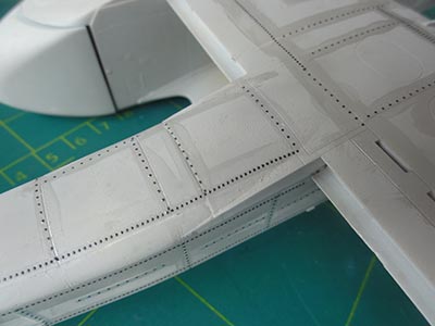
The surfaces are rather smooth with inscribed panel lines. On a real Bronco however various raised rivets are soon. (see walkarounds on the IPMS.NL website). Raised rivets are seen at many places like fuselage sides, tail booms and tail. Also on the gear doors.
On this 1/32 scale it is worthwhile to add these.
MicroMark raised rivets decals are great for this. I used them previously on the 1/32 scale Lynx and also FAV T-2 Buckeye.
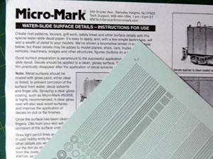
Various decal lines with these rivets were set onto the model. This took a couple of hours, continuously checking with the walk around photos.
STEPs 5, 17, 24 + 25
The trailing edge flaps, ailerons and elevator were also installed so the camouflage patterns also cover these in the pattern. This was no problem and all moving surfaces fitted nicely and were set at a drooped angle: the ailerons slightly down respectively up at the other tip.
Also the pylons were set in place as desired included the central pylon for the big fuel tank.
Now the model needs careful handling as not to damage the vulnerable rivet decals. Particularly when any masking tape is used at later stages, this will easily tear off any decals. So as precaution, once the raised rivets decals were applied, another thin coat of steingrau was airbrushed. This will help a bit.
page 2
real bronco
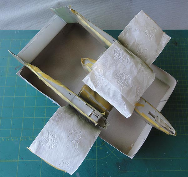
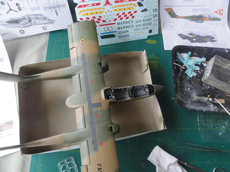
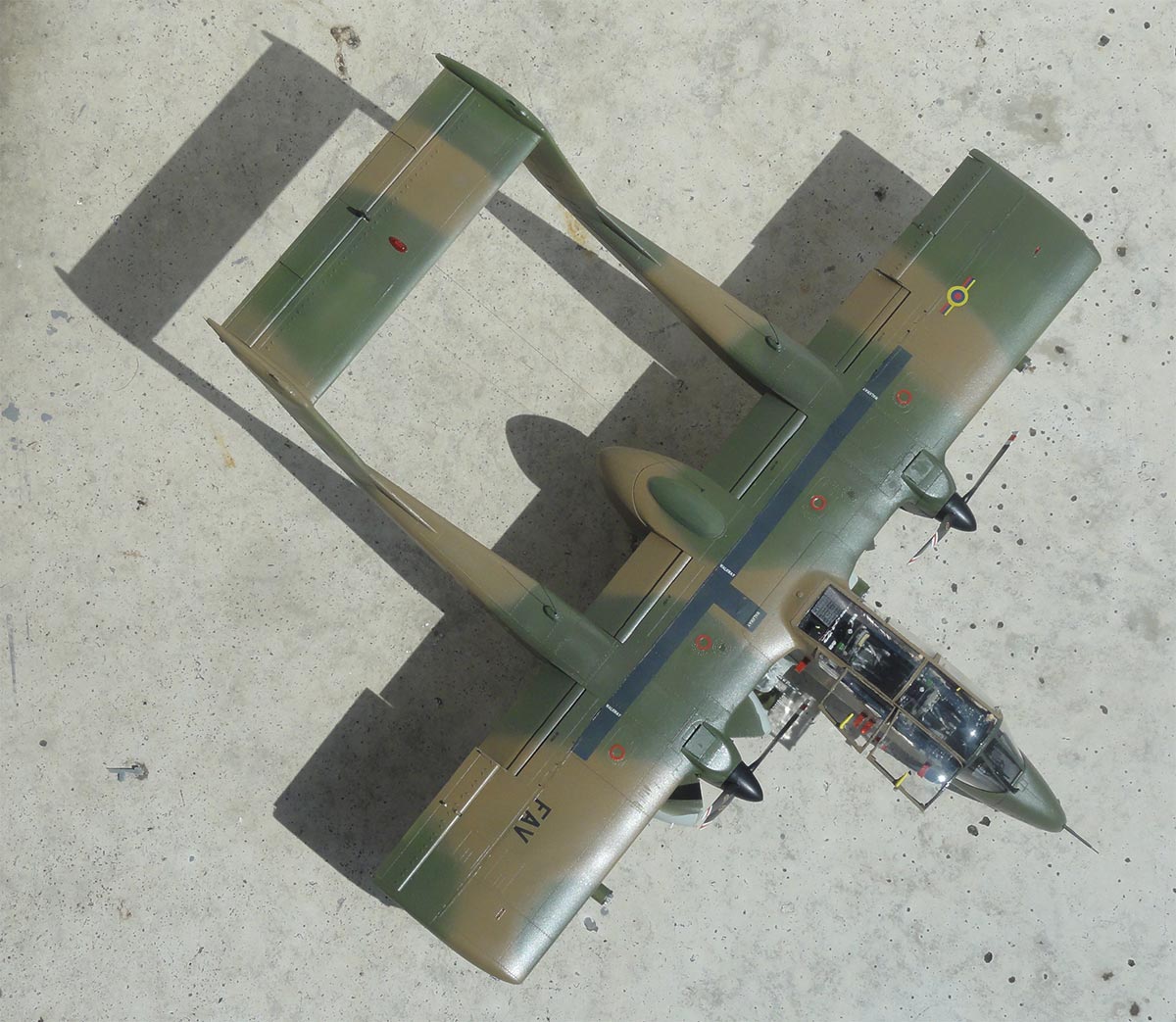
The camouflage pattern is now to be airbrushed. On the Bronco various patterns are seen. It appeared that for the Venezuela OV-10E the "Vietnam style" pattern "E" shown by Kitty Hawk is applicable.
These Mr.Hobby Gunze Sangyo acrylics were airbrushed:
- lower grey Federal Standard FS36622 Gunze Sangyo 311 ;
When dried, mask these lower areas with tape and paper.
Next...
- green FS34102 Gunze Sangyo 303;
- darker green FS34079 Gunze Sangyo 309;
- brown FS30219 Gunze Sangyo 310.
The soft demarcations were achieved by holding a piece of carton to mask and low tack masking tape.
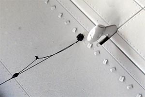
The rivets are seen here for example on one of the tail booms and look great.
![rivets]](bronco-rivetting.jpg)
I now turned to detail the cockpit
STEP 1 Cockpit
INSTRUMENTS
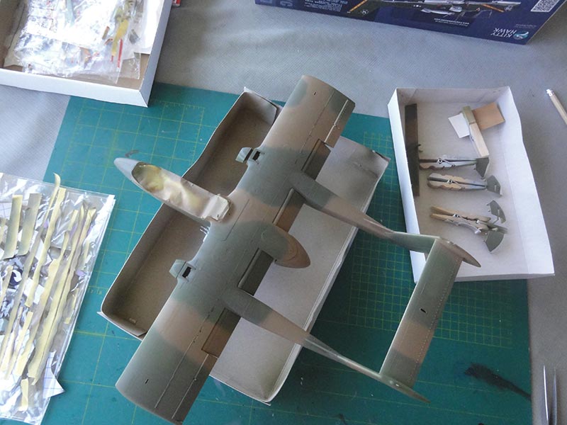
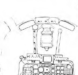
The instrument panels were checked and adapted according to the real aircraft panels as seen on the detail page here.....
On pilots' forward panel on the OV-10A does not show an indicator at the left section, but a UHF comm panel (numbered #44 on the detail page). Simply a piece of thin plastic was set on top of the indicator.
On the rear panel more changes were made. In the upper section more indicators are seen in a wider panel and also indicators #11, #12, #15, #16 are different. (see the info page here...). Also the landing gear control handle (technical drawing no.42) was made at the front panel.
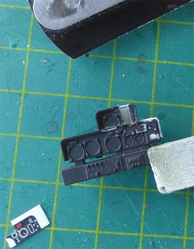
With a razor saw the upper section was cut and with card made wider. From the instrument decals some left over indicators were set at the various positions.
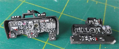
On top of the instruments to suggest glasses drops of Microscale Kristal Kleer were added.
The side consoles and details look good in the kit and accurate. The raised detail can be painted with the main colour being black on the console pads and various white/grey knobs and switches. Some smaller bits were added from scrap.
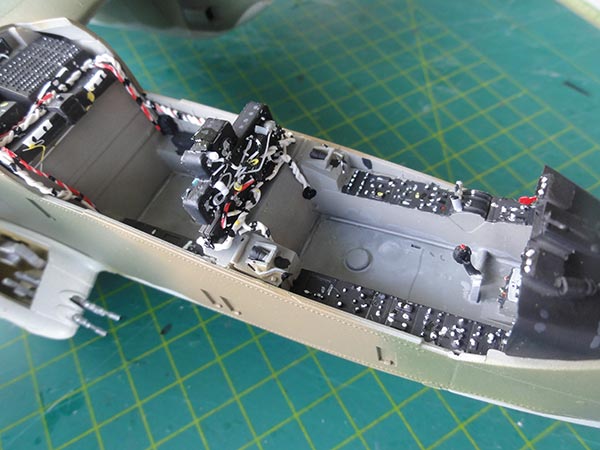
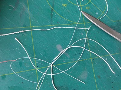
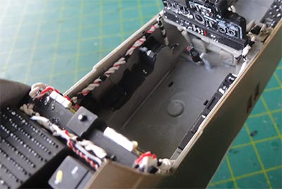
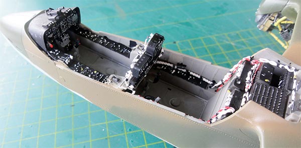
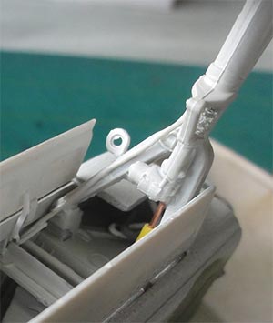
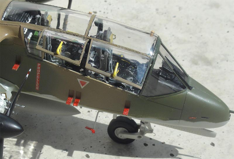
What is really missing and highly visible are electrical white wire bundles, mostly running from the central instrument panel to the rear of the right cockpit tub side. Also at the rear avionics boxes these are seen. These white wire bundles were made from thin real white electrical wires twisted together and set in place with superglue. Some red wire was also used.
SEATS
The LW-3B ejection seats in the kit look fine but can be improved. I believe the parapack container (part #I18) positions varies between seats. Always one should be positioned on the port left side and one of the starboard side on the other seat. So adapt this assembly.
On the seat I added sort of leather cloth I had to suggest the seat cushions.
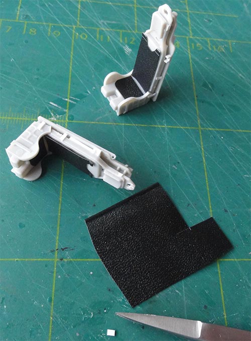
I also had a gap between the rear frame #H27 and the seat back #I4 so added a piece of card. In the shape on top of each seat, the "canopy breaker", a hole was made
The basic seat was airbrushed FS36231. The cushion colours vary, I painted them light green. The head rest cushion was painted sand and the parachute containers green.
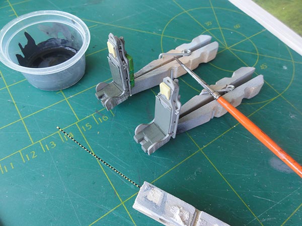
KITTY HAWK provides nice etched metal seat harnesses. These were painted light grey, the buckles metal.
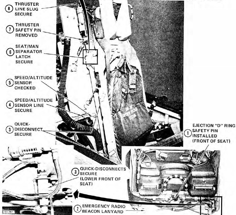
Missing on the kit seats are a few handles: one at the port side next to the head rest. Another large ejection handle is missing at the front. These were made from bended yellow electricity wire with black painted stripes.
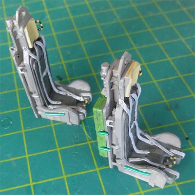
Some wash was added and the seats will be installed later on in the cockpit tub.
It is now time to add the scheme and decals as the model had all its paints and camo's and can be handled. But first the model got several coats with varnish, I used Johnson Future / Pledge with the usual airbrush technique. This to minimize "silvering", the effect of trapped air bubbles below the decals that spoils appearance.


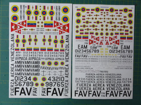
The scheme for the VENEZUELA OV-10E was picked as an initial old style Bronco with the conventional markings prior to the "Chavez revolution". I had national marking decals from AZTEC set 48022 with a large variety of sizes.
I studied photos and drawings and concluded that the markings are rather small with a length of the "roundel with bars" of 20 mm in 4 positions and the 2 FAV titles were 20 mm long as well.
The flags on the tail are 10 mm wide. The 2 small tail code numbers were also found on the sheet so all are on the AZTEC sheet.
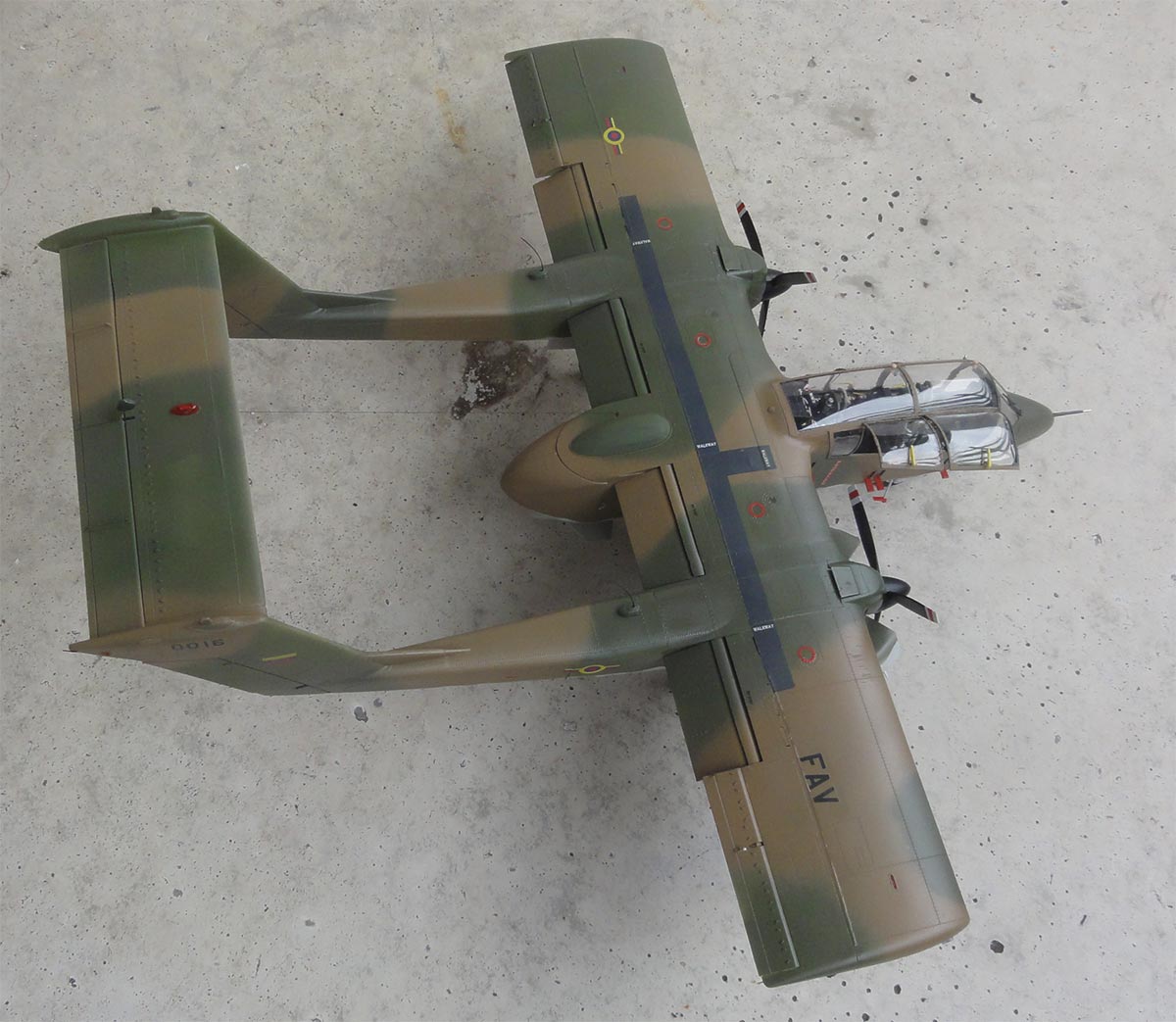
What is not provided by KITTY HAWK is the often seen "walk way" on top of the wing. I airbrushed a flat decal sheet dark grey and cut decal stripes for the walk way sections. I estimated the base walk way width to be 7 mm and the overall length 200 mm.
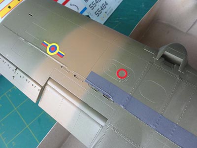
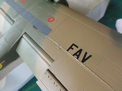
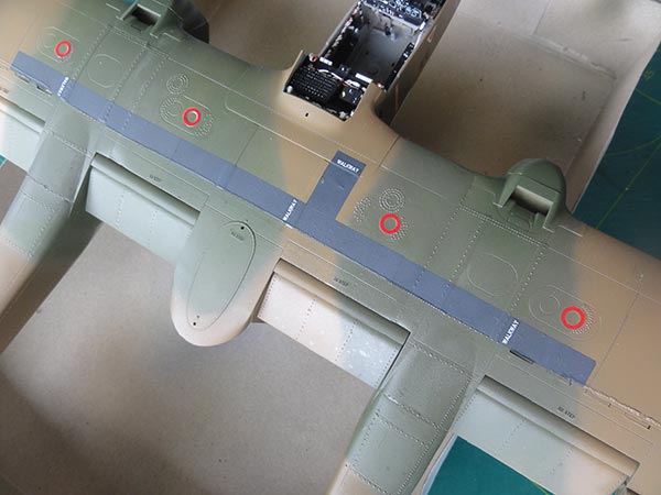
The white "walk ways" texts are provided in the kit and put on top.
Once the decals were dry, a light mist of the lower camouflage colour was airbrushed over each decal. Just slightly, this will "blend" the otherwise rather obvious decal into the surface. Particularly the red "filler cap" markings look than much better.
Further assembly of parts and details were now tackled.
STEP 5
The bulge on the fuselage top #F21 was painted olive green and installed.
STEPs 13 + STEP 20
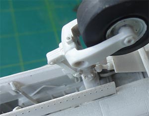
The landing gears were now set in place, including the nose gear seen in STEP 3.
The various gear legs were prepared at an earlier stage. At the absorber in the strut a piece of metal foil was wrapped around the oleo.
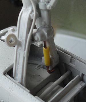
It takes time, sometimes I had to trim their locating notches. Take care not to break the plastic while putting pressure!
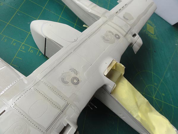
Inside the gear bays some hydraulic tubes were set made from scrap, particularly at the forward section of the main bays. A large missing actuator was also added, made from thick electricity wire (seen yellow above, to be painted). The gear doors were also positioned.
The nose gear bay also got some detail, as seen in STEP 3. Like the gear door rods #G4.
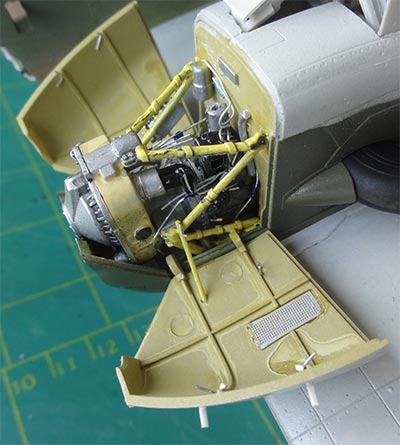
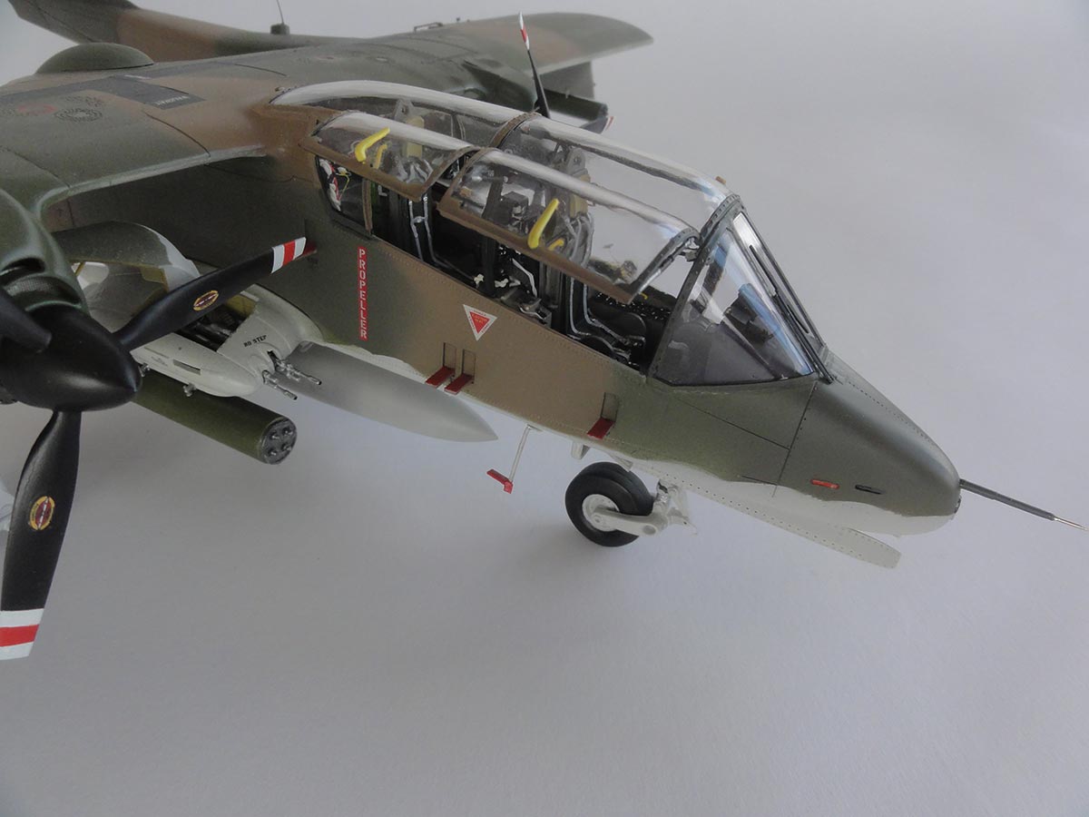
STEPs 11 + 23 ENGINE
One engine only was to be set in place with one cowl open with the access doors. To install the engine assembly I removed from the frame rods at their bulkhead attachment points 1 mm to ensure the upper cowling section fits.
The cowl doors locating lugs (see step 23) needed to be cut a bit smaller. On the cowl doors locks were made and the handles. Note also the etched metal grid inside the cowl door. There are still a few sink marks, so on your model remove these more carefully....
As the other cowling will be set closed, in order to fix the propeller at the closed cowling a small card piece with a hole was set in place. The panels when closed showed some tiny gaps, these were filled with white glue and painted in camouflage.
The two engine exhausts #A12 are a bit undeep but I simple painted them gloss black inside.
The model now got a semi-matt varnish coat as the glass work is not yet installed. This will give an even sheen and protect the decals. Johnson Future thinned with 40% Pharmacy Alkohol was used with some 20% Tamiya matting acrylic X21 "Flat base" mixed in.
When dried for 24 hours, the next steps were handled.
VARIOUS LIGHTS
The anti-collision lights are nicely provided in the kit. The wing tip lights #GP24 were painted red and blue on their inside surfaces. But they needed trimming to fit so got an additional transparent paint using TAMIYA clear acrylics.
For the larger lights #GP26, GP27 on the horizontal stabilizer and lower fuselage I inserted inside these a red piece of rod to suggest the light bulb. The gaps in the plastic positioning surfaces were closed with white glue; once dried these patches were painted aluminium, to suggest the light reflector.
The smaller glass parts #GP10, GP11 in the fuselage nose seem to be also anti-collision lights. These needed trimming and making smaller to fit in their recesses. They were painted red on their insides as well. The clear nose light #GP23 needed some trimming as well and got a metallic silver bit at the inside for the reflector.
What is missing is a small anti-collision tail light at the end of the left tail fairing. This was made from scrap.
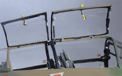
"CANOPY GLASS WORK"
TAKE CARE WHEN SEPARATING THE CLEAR PARTS FROM THEIR SPRUES; USE A FINE RAZOR SAW.
When setting these transparent parts it is difficult to choose the suitable glue: superglue runs a risk of "fogging" later on, plain glue dries quite slow and white glue can also be used. So take your time here.
STEP 6
The wind screen frames were painted black inside and the outsides of frames to match the surrounding camouflage pattern. The windscreen fits but needed a tiny filling with White Glue to close the small gaps. Paint when dried with a paint brush.. (As noted earlier, for this OV-10E [OV-10A] I did not use the nose bits #A16, A17 as seen in assembly STEP 6).
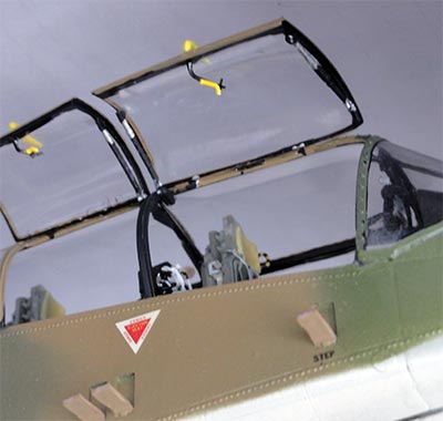
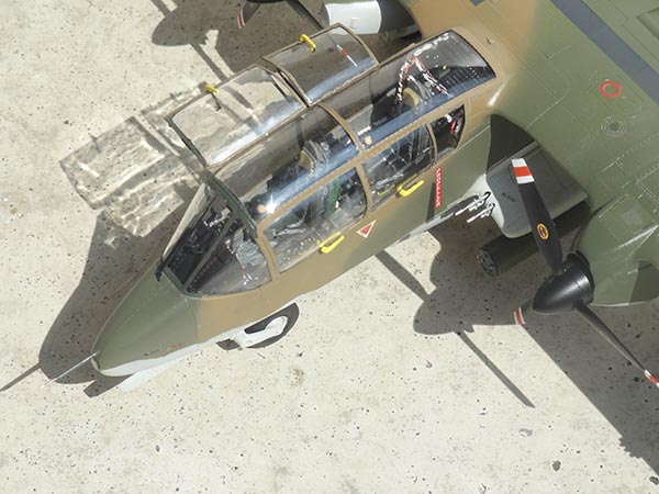
STEPs 9 + 10 CANOPIES
The canopy panel frames were also painted black inside and their outsides of frames to match the surrounding camouflage pattern. These clear parts need care to align. Take your time as it will spoil the model is not carefully done. Avoid glue spills.
The 2 right canopy panels will be set open, the left side closed. The central structural frames #G9 and G10 seen in STEP 6 are set but needed a bit trimming to fit.
The central canopy panel #GP3 seen in STEP 9 needed a little bit of sanding at the mating front and rear side surfaces but fits.
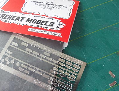
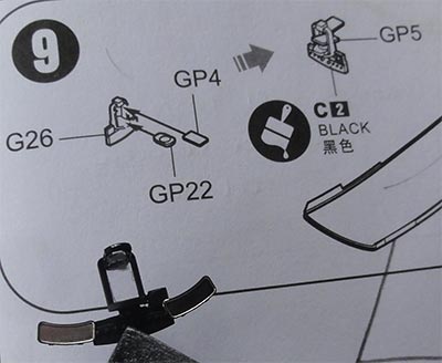
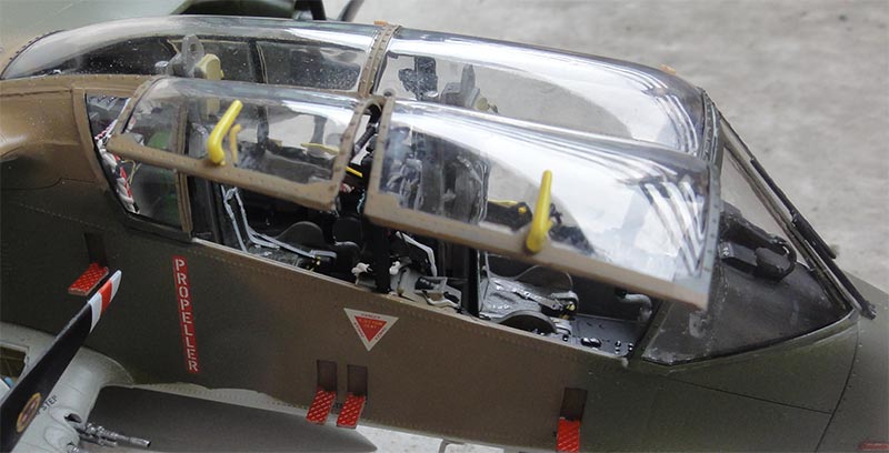
The optical gun sight #G26+GP4+GP22 is nicely provided. But I saw on many Broncos 2 large mirrors next to the gun sight. Also in the mide frame for the observer 2 mirrors are often installed. This are missing in the kit. So from a REHEAT etched metal set these mirrors were installed.
The rear panels parts #GP19 have 2 options: with a small engraved frame or clear. It is difficult to see on photos. I picked the ones without frame. The rear panels will fit, a little White Glue was needed to fill the tiny gaps. Paint when dry.
The various entry steps were set open, see STEP 6. The retracted LADDER (illustrated as parts #F38+F44 in STEP 8) were not used, but a extended LADDER made from scrap.
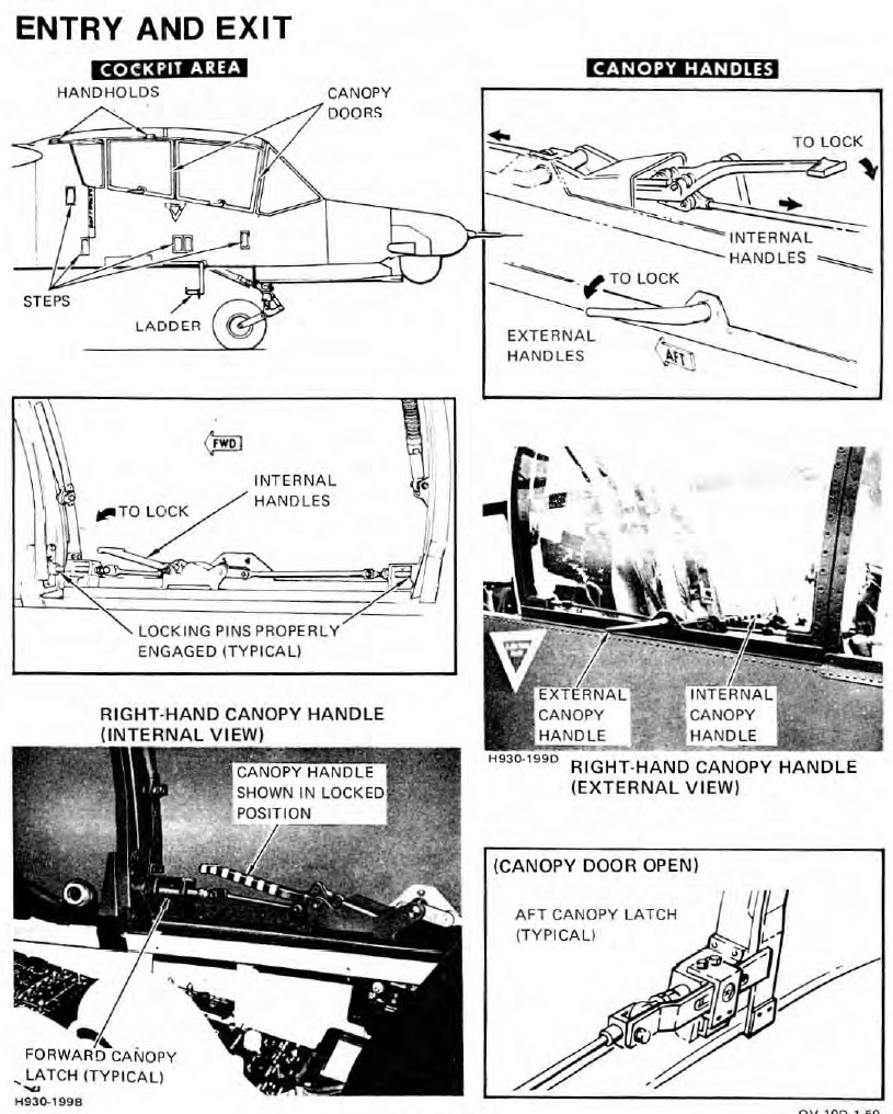
The various outside canopy panel handles (parts #H48) were set. For open canopies the handles are set vertical at 90 degrees, for closed horizontal. On the inside also each crew member can operate a large handle and that is visible on each opened canopy panel. This was made from scrap and colours vary from black or yellow.
Inside the forward canopy the optical gun sight with 2 extra REHEAT mirrors was installed. A small indicators was set next to the right pilot mirror. Also I added a tiny cooling fan made from scrap at the observer station below the central frame.
 .
.
The fixation rods, kit parts #H28, are also often seen "stored and folded" inside the frames as done on this kit, even when the panels are open. The central bars #I49 are nicely provided and set in place. The panels often also show various vents and sensors (may vary between Broncos). These were made from scrap.
STEP 17
Below the wing the outside pylons "stations 1 + 7" were set in place. I added a 2 tiny structural panels at there base and store fixation rods from scrap (similarly as parts #I10- I13 seen in STEP 7).
The panels on one of the gun stubs on the right fuselage side were set open to show the guns. The guns details as per kit were added like the gun ammo feeds. I also added a few electrical wires inside.
STEP 8
It was decided to close the rear fuselage auxiliary cone/ door. It was simply set in place. A small door handle on the right cone side was set horizontal (not vertical as instructions illustrate in STEP 10).
STEP 25
The actuator rods #PE8 were installed at the elevator.
STORES
The Bronco model would get some weapons/ stores. I opted for, as noted earlier, one open gun stub, a fuel tank and rockets pods.
On each inside pylon a 2.75" rocket pod as per kit was set with their fixation braces (parts seen in STEP 7). The front and rear was painted dark metal, the pod itself olive green.
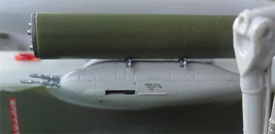
The outside wing pylons got 5" ZUNI rocket pods as per kit. It is a bit confusing how these pods are configured. I saw photos with visible rockets but also only holes, so used also part #H40 (not shown in the instructions on page 22 and not #H65). Here also the front and rear was painted dark metal, the pod itself olive green. A few fixation braces were added from scrap. Note that the gap/ slot in the stub is actually there, I think these are gun gass vents.
The central 260L fuel tank as per kit was set in place. I needed to "lengthen" the stabilization fixation rods #F30-F33 a bit with scrap rod. The tank overall colour is the same as the lower surface FS36622.
The final smaller parts installed are:
- nose pitot tube #A13, see STEP 6; I replaced the front tip with a metal needle. The nose light #GP23 was installed but required a bit trimming. I set a metal reflector from foil behind it.
- on the nose gear leg, I saw a small towing hook; this was added from scrap.
- add the actuator rods on the ailerons as seen in STEPs 17 + 24. Also 2 tiny upper and lower balance horns were added on each aileron (missing in the kit);
- 2 antenna fairings #H33 (see STEP 15) were set in place so on both tops of the tail booms. And two UHF / FM antenna wires added from stretched sprue on top of the tail booms.
- the antenna #A21 seen in STEP 10 was not fitted on Venezuelan OV-10's. I saw a small round base and a piece of rod was set in place.
- a small IFF antenna was set below the right tail boom from scrap.
- static dischargers were made from stretched sprue: one below each wing tip, one on each rudder and one on each vertical tail top end (so 3x2 = 6 in total).
- the long antenna wire as added that runs from the fuselage top to the stabilizer. It starts at the left side of the bulge #F21 seen in STEP 5. I used fishing line that was painted black.
That completed the model!!!
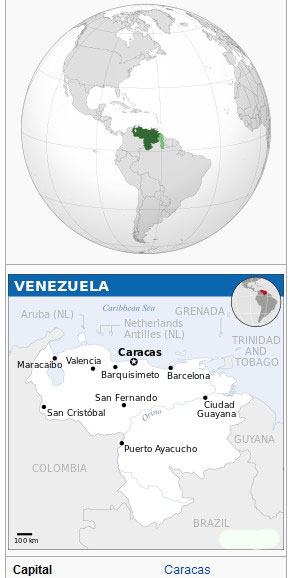


[ area: 916,400 sq.km | population <24 million | capital: Caracas | GDP per capita nominal < 1,000 USD crisis ]
See more Venezuela FAV info on the T-2 page here....
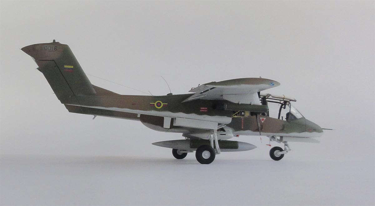
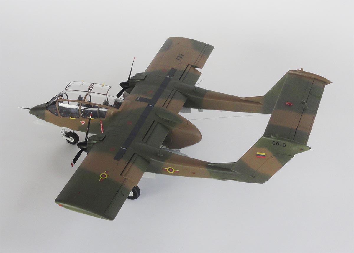
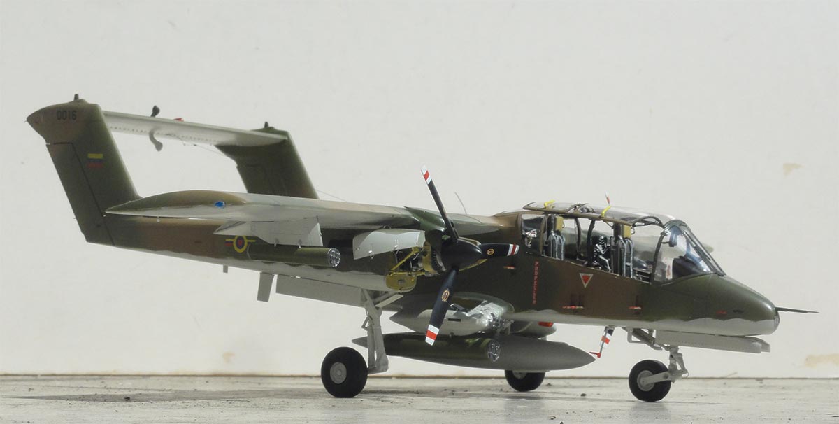
OV-10E , Fuerza Aerea Venezolana (FAV) , 2 Grupo Aereo, 1991.
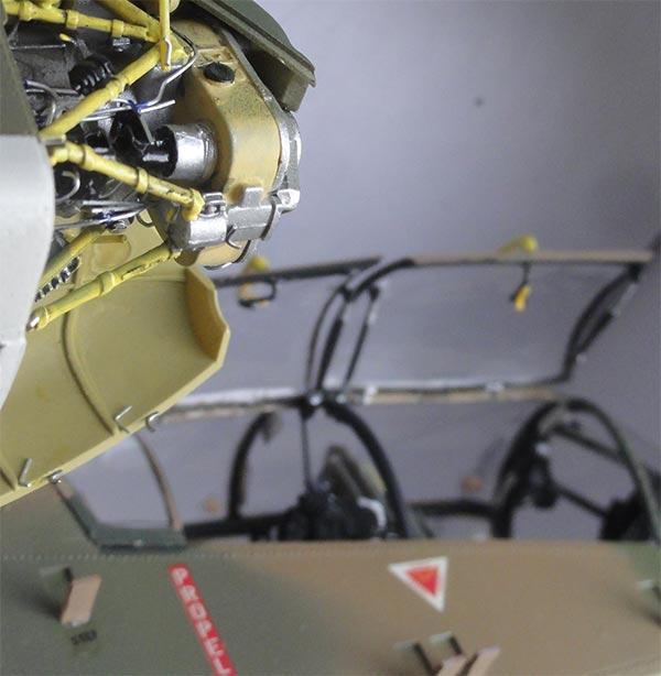
Some details of the opened engine cowl.
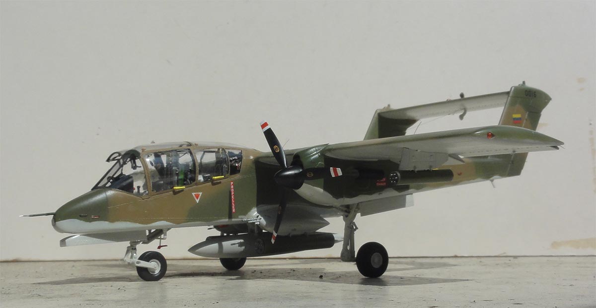
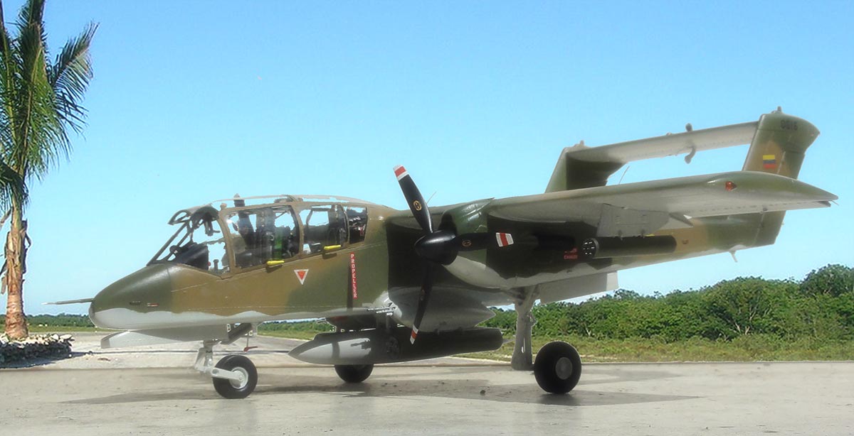
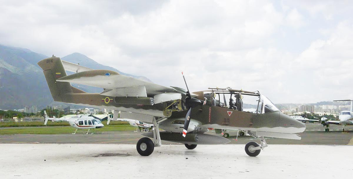
OV-10E on a visit to Caracas, Venezuela
A nice 1/32 Bronco in the World Air Force in Plastic collection.
(c) Copyright "designer"/ All rights reserved. Your comments are welcomed by webmaster
Created this page June 4, 2018