[page 1]
Italeri Lockheed X-35 JSF,
1/72 , kit no #1209
NOTE: photos in this modelling report are small, made with the first generation digital JPG camera in 2000
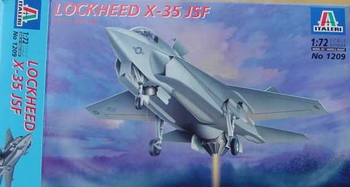
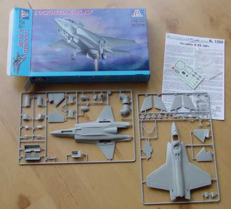
The Italeri kit of the X-35 is the second JSF model from Italeri, next to the X-32 of Boeing. The kit is typically Italeri with good parts and the usual instructions.
It represents
a X-35A, the version with a SVTOL system behind the cockpit and rotatible
jetpipe.
The real X-35A
flew first as a prototype, now it is being converted to the X-35B.
The X-35C is
the Navy version with enlarged wing tips, separate aileron and larger horizontal
stabilizer. It also has an arrestor hook.
The model depicted here, as provided by Italeri, is the X-35A.
However, unfortunately the kit has some serious errors:
1- The
wing fairing at the cockpit sides should have a little less width, remove
1 mm.
This will also
give the wing-fuselage junction the needed small kink at the wing Leading
edge at the root. Remove some plastic, fill and sand smooth.
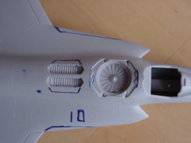
some suggested
corrections outlined in blue,
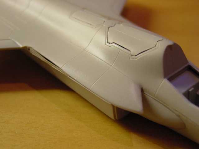
2- The engine edges of the fuselage needs to be straight , so cut and sand.
The two lower
fuselage "belly" bulges on part 11 at the main undercarriage sides should
be removed; sand these flat.
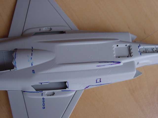
note the belly
fairings, to be sanded flat
.
3- Nose undercarriage doors and bay should be straight, not with those "stealth" edges.
Correct all doors, the main undercarriage door needs to run more inboard, so make a new one of card.
Main undercarriage should be moved approx 5 mm more forward, and reduce the length of the main bay. In fact, the bay opening should extend somewhat more inboard on the flat lower fuselage (not yet seen at the pics...)
The legs should
also fit into the fuselage and not into the wing.
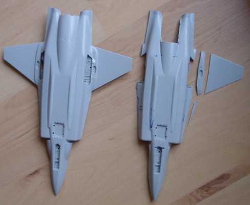
two fuselages of two kits: right with cut- out parts to correct it further. Right part not sanded flat yet.....
The bulges (15/16) at the intake should run a little smoother, so use some putty here. Sand first before added the intakes (31/32).
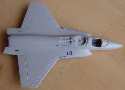
Glue main parts
together, fill and sand smooth.
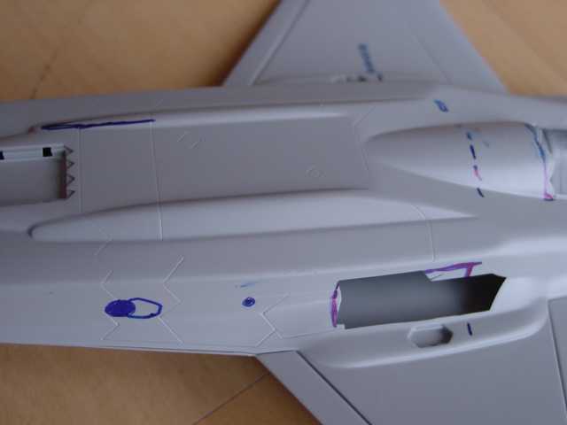
the leading
edge and intake area with removed
1 mm width.
Lower fuselage wing junction corrected with cart. Also the belly was sanded "flat".
Note that the main u.c. bay opening above is not yet correct, this is shown below....
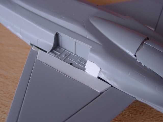
The main u.c.
bay opening is extended to the flat underside.
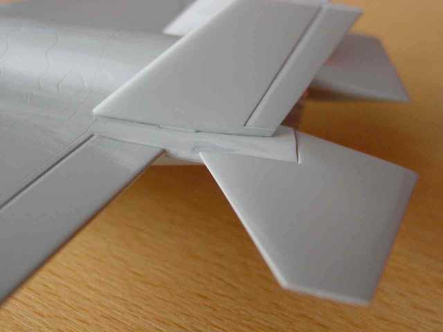
The vertical
tailfins are OK, but they should be fitted 1 mm more outboard. Cut out
the outboard edge of the locating holes and glue the fins in place later.
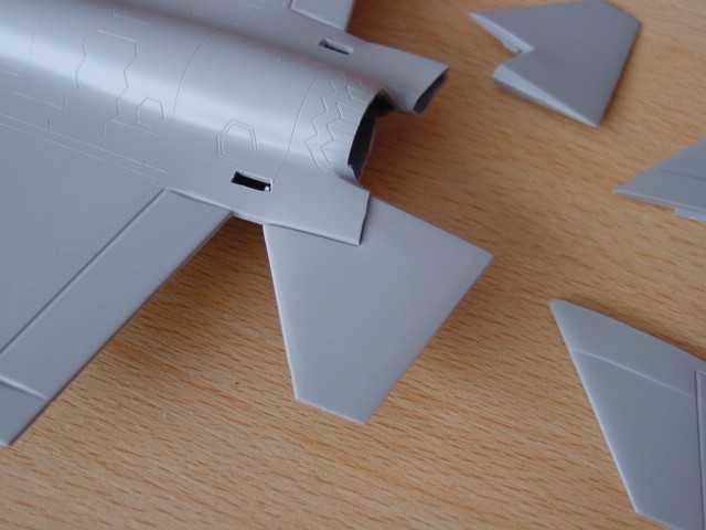
The tail area: note extended slots for the vertical tailfins to move them more outboard.
When you built
this kit:
- The cockpit
will benefit from adding some more detail.
- The small
intake doors on top, on the left side and APU are missing before the wing
LE.
- Add some
antenna?s and the nose pitot if desired.
- Add a fairing
at side of the lower left main undercarriage door. Not yet seen on the
pics...
- You can also
add two thin brakes at the lower fuselage at the rear (not provided and
not yet seen at the pics here...).
A small set of decals is provided for a X-35A prototype but they are not correct .
If you want
to make a US Navy SVTOL X-35C adjust the following:
- make the
larger wingtips with separate aileron. Extending the tip will do the job.
- add the lower
aileron fairings
- add an arrestor
hook and fairing
- fill the
door aft of the top intake on the top of the fuselage and add refuelling
panel.
- extend the
horizontal stabilizers slightly and change the hinge line of the stabilizers
aft of the vertical fins.
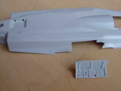
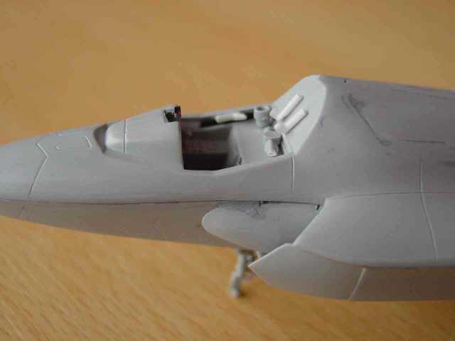
The tail surfaces added, with white glue used to fill the smaller gaps. The vertical fins are mounted more outboard now.
The main intakes are added as is the nose undercarriage. It has newly made doors from card. Also note the closed and filled auxiliary doors aft of the n.u.c. bay.
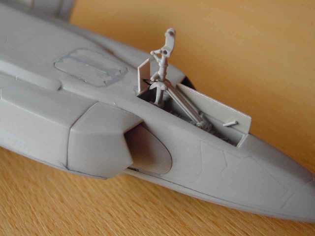
cockpit area
with some added sprue details. Some sanding work to be done still...
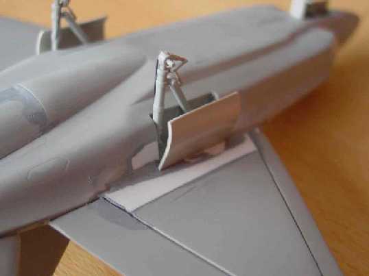
Note the correction
at the wing fuselage junction and single piece door of card. The
engine covers are also in position. The wing flap and slat gap are left
open. The APU exhaust is added in the forward fuselage and the main wheel
struts added, needing only cut-off of their locating pins.
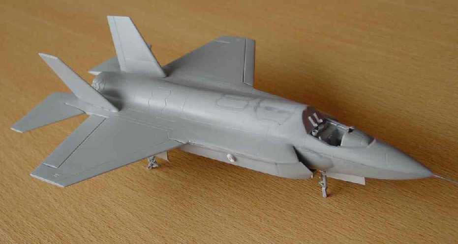
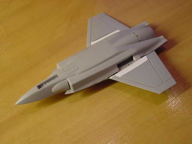
A view of the
model prior to final clean up and ready then to get its first grey base
coat. Pitot tube added from a needle and exhaustpipe (APU?) on the right
intake
References:
- Lockheed Martin website
- Air international , December 2000
The mock-up
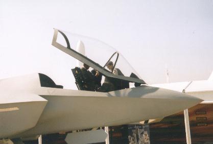
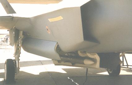
The Real thing
The X-35
STOVL version with rotated exhaust is shown below. Note opended doors next
to the jetpipe and the 2x2 opened doors on top of the fuselage just aft
of the cockpit.
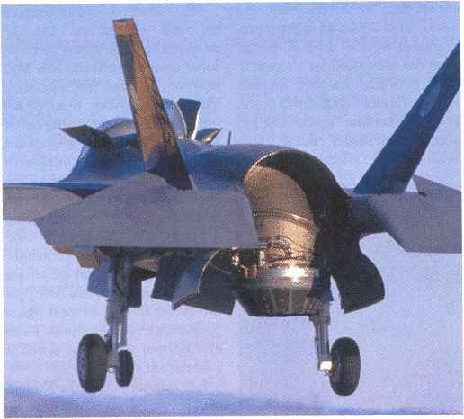
Photo: Lockheed
Martin

(c) Copyright Meindert "designer"/ All rights reserved. Your comments are welcomed by webmaster
Created
February 3, 2001