1/32 scale conversion
[ page 3 ]
Tornado ADV model in 1/32 scale
...continued from page 2...

KIT STEPS 10 & 11
Leave the fitting of the upper CRT
screens for later.
KIT STEPS 12 & 13
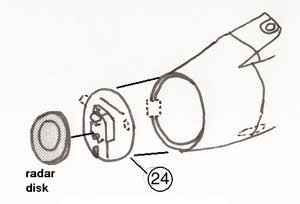
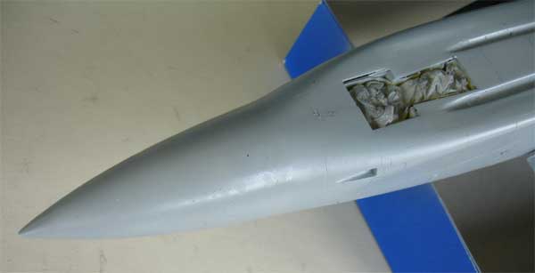
The Tornado ADV has a pointier radar
nose as compared to the Strike IDS or ECR Tornado’s. The kit radar nose
#28 and ring #27 are not required, simply replace by the resin radar nose.
Remove on the inside of part #18A the hinge stub. Fit the kit pitot # 102
to the resin nose at a later stage.
Now make sure that the resin nose fits well. It has already been slightly prepared for you, but with a flat sanding block make a straight rear end and dry fit all the time until you get a good fit to the forward fuselage. The vertical symmetry line is indicated by the line and small notch inside the resin nose. Note that the nose points down on the Tornado ADV. Fill the tiny air bubble holes with putty and sand the radar nose outher surfaces smooth.
Fit the nose and some filler is required.
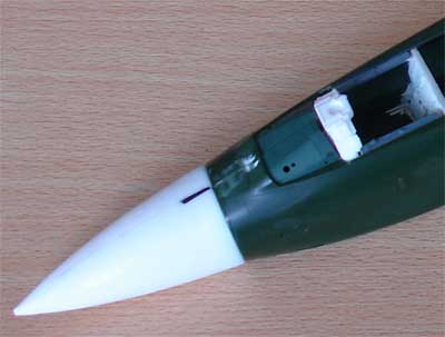
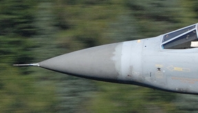
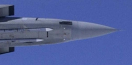
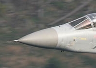
On this picture
the nose may seem a bit strange with the curve. But look at actual Tornado
ADV pictures as seen here and you'll see it is correct!
 .
. .
.
Note: the resin radar nose is hollow, and can be set open to display the radar. It is suggested to use a metal rod (such as from a paperclip) to get a strong hinge to show the radar swivelled open.
The inner edges of the resin nose
are not always symmetrical, but symmetry can be improved by adding a tiny
ring from plastic card. Replace kit part #25 with the supplied larger ADV
resin radar disk and discard part #26. The bulkhead #24 can be used with
slight modification.
When you want an open nose, do not
fit the radar details at this stage but do so later on after you completed
the overall airframe assembly.
![]()
Continue now with…..
KIT STEP 53 (RAF kit 04705 steps 52-53)
The ADV has a single Mauser canon
on the right side, so the gun nozzle was filled in previous stages. (on
the ECR kit use part #207).
The Tornado ADV has slightly different
scoops, fairings and antennas. Check references as there are small differences
between aircraft.
Do not fit part #204 but indeed close
the left gun nozzle opening with part #207. Fill and sand smooth.
The probe #109 is more forward on
the Tornado ADV. Fill the locator gap and re-position as indicated on the
fuselage side drawing.
It is now recommended to check the fit of the forward fuselage to the rear fuselage. Tape together the main kit fuselage parts #54 and #48. Now dry fit the forward fuselage. Also dry fit the supplied resin rear jet exhaust pipe plug. You now should have an idea on how it all looks.
KIT STEPS 14 up to 22
Assemble as required: wings, pylons,
stabilizers, gear bays. The pylons can swivel as suggested by Revell, but
better leave them off and fix in place much later. For the F.mk.3, two
additional Sidewinders could be fitted outboard on the wing pylon; use
the two resin made pylons.
The wings should be put in place now,
but you may desire to paint the wings first as the swivelling area can
be more difficult to reach. I opted to spray and paint the wings later
on.
Do not fix the stabilizers to the
model yet at this stage. Find a way to fit them later on and not using
part #47 but to fix the stabilizers another way with a metal rotating pin
(made from a paperclip for example).
KIT STEP 24
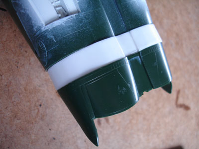
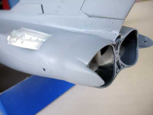
The Tornado ADV F3 has Rolls Royce
mk.104 engines with a longer afterburner.
Note: If you want to build the F.mk.2, simply skip the jet pipe extension and build the kit as per instructions.
Insert for the F3 the resin extension plug between the kit’s rear fuselage and the end part #61. Putty and sanding is needed. Re-scribe the panels in the area. I always use an Olfa P-cutter.
Fix the jet pipes and reverser parts
#66 + 67 later on in step 25.
Inside the fuselage, it is recommended
to fit some plastic card to suggest intake tunnels for the engines, although
not a lot will be seen.
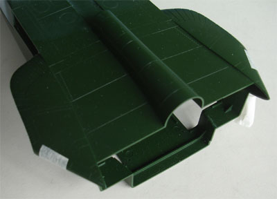
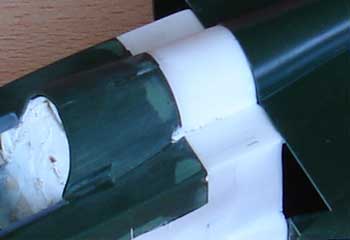
Fit the forward fuselage to the rear
assembly. Putty is surely needed. It may be a good idea to glue on a thin
section of plastic card on the lower junction. It will help to get a stronger
junction and a straight flat area.
 ..
..
..
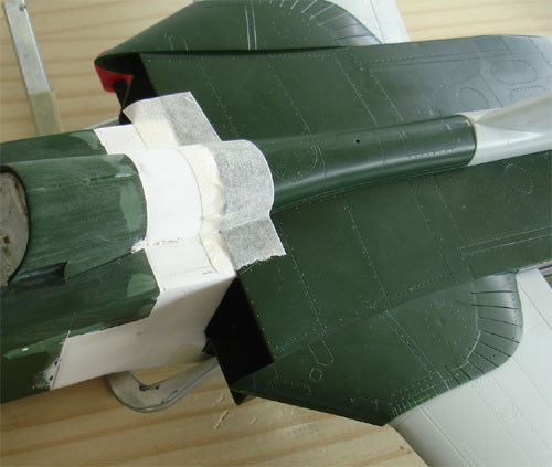
Fill and sand as needed. Once the
filler is sanded, you'll see that minimal filler is needed.
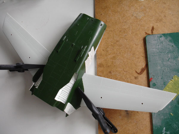
The Tornado ADV has a more swept wing
glove root section and no lower Kruger flaps.
Two resin glove parts were fitted and sanded flat with a sanding block. Dry
fit the port and starboard resin parts to the kit gloves and sand the inner
round edge with a round file. (NOTE the difference between port and starboard; they should point down a bit representing
an airfoil). Fill with generous amounts of putty on upper and lower
areas.
Fill the kit' inscribed lower Kruger flap
panellines on the kit parts as they are not present on the Tornado ADV.
 .
. 
KIT STEP 26. (RAF kit 04705 step
“unnumbered”)
Assemble as shown, starting with
the prepared forward fuselage. This will need some putty to fit between
the resin plug and rear fuselage. Fit the vertical tail later….
KIT STEP 23
Tornado ADV F3 has an almost straight
trailing edge at the fin root. Replace kit parts #59+60 for the F3 with
resin tail fairing part, remove the tiny stub. Trim the resin part. Some
putty is needed.
Note: The vertical tail parts #58, 59 should be used for the F.mk.2 as it has NO jet pipe extension.
Two blade arials are on the ADV fin.
The RAF kit 04705 has them as parts #165 as seen in step 75. Fit on the
ADV. On other kits, make two blade arials from scratch (triangular 11 x
9 mm).

Fit the vertical tail now to the upper
fuselage.
 F3
F3 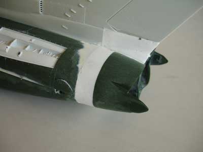
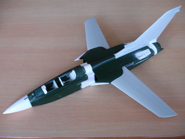
The result up till now..... next step
is fitting the intakes....
![]()
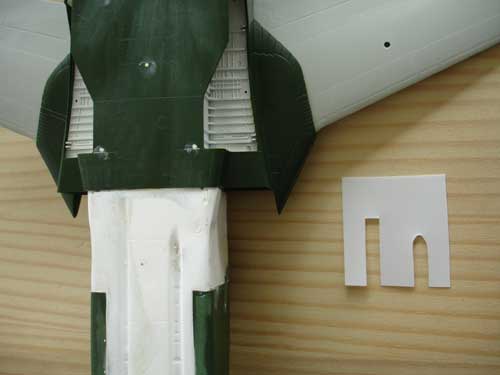
KIT STEPS 27-30 (RAF kit 04705 steps
26-29)
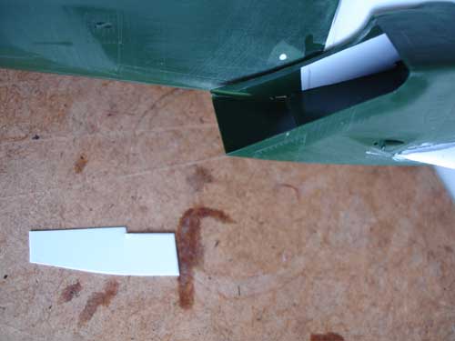
Assemble the intakes. There is a
strange triangular gap in the inner intake side of each; I covered these
gaps with very thin plastic card.
The intakes
should fit the rear fuselage and the resin plug as inner section. Remove
positioning pins on backs of intake plates #69+73.
KIT STEP 53 (RAF kit 04705 steps 52-53)
The ADV has a single Mauser canon
on the right side, so fill the gun nozzle. (on the ECR kit use part #207).
The Tornado ADV has slightly different
scoops, fairings and antennas. Check references as there are small differences
between aircraft. Leave these for later assembly to avoid damage.
Do not fit part #204 but indeed close
the left gun nozzle opening with part #207. Fill and sand smooth.
The probe #109 is more forward on
the Tornado ADV. Fill the locator gap and re-position as indicated on the
fuselage side drawing.
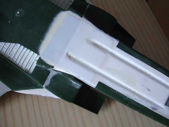
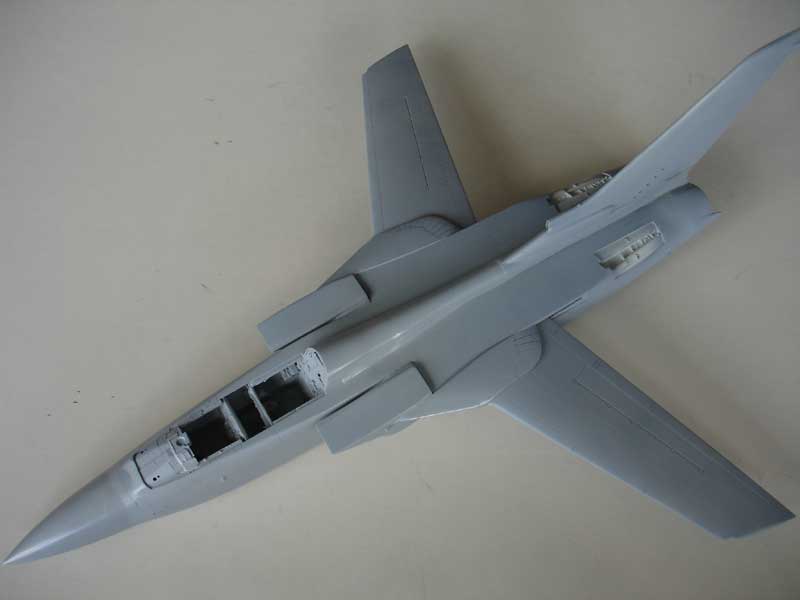
The major airframe parts have been assembled. Next, re-scribe some panellines. Fill small holes with putty or Mr.Surfacer liquid putty and sand the whole model and clean up. It is a good idea to spray an overall coat of light grey paint primer to check for any flaws.
![]()
It is now a
good idea to spray an overall base primer coat of light grey to check
for any flaws. Than do some extra puttying to get a perfect result. The result
below is seen after a single pass with light grey with the airbrush. At
first impression, it comes out pretty well.

Note that the ADV Tornado has a very particular shape of the nose where it meets
the main fuselage just like in the real plane
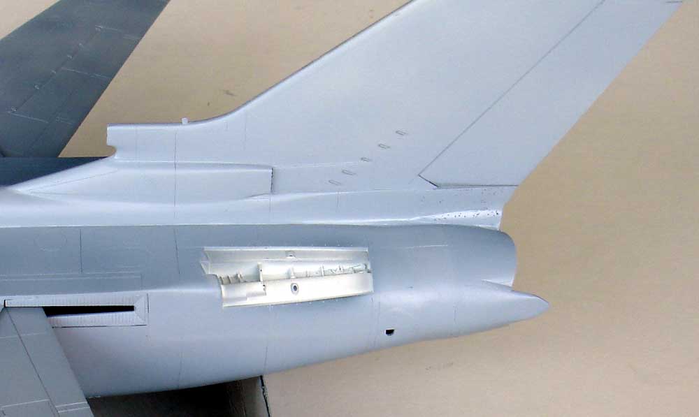
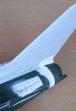
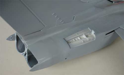
Here the rear section with extended jet pipe
area
Some tiny holes
still to be filled in the fin base (e.g. use Mr. Surfacer liquid putty
for that)
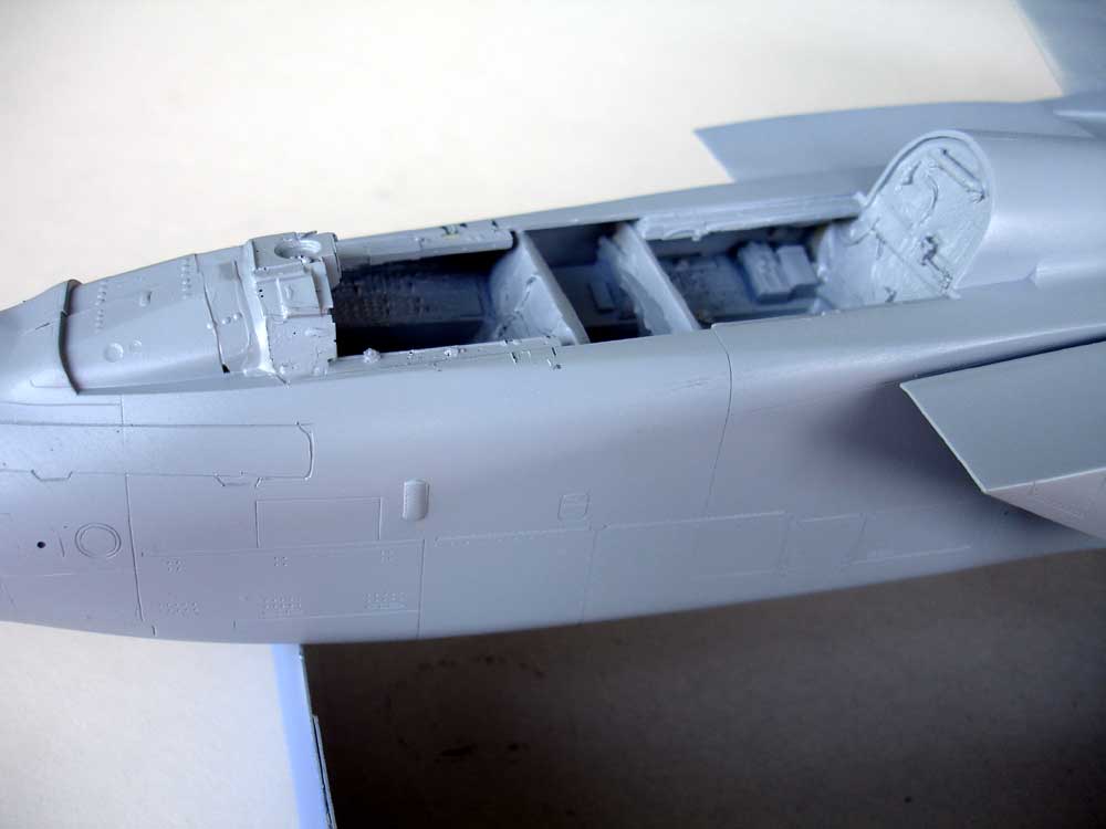
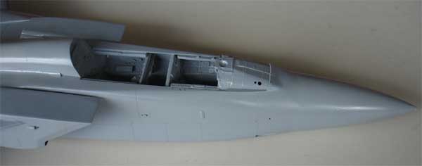
Forward section, note inscribed refuelling
system doors
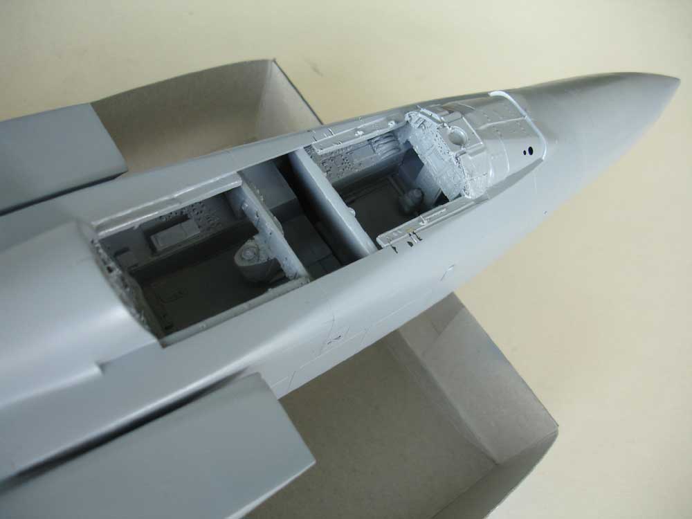
Details still to fitted in to ADV F3
cockpit but the basics are there
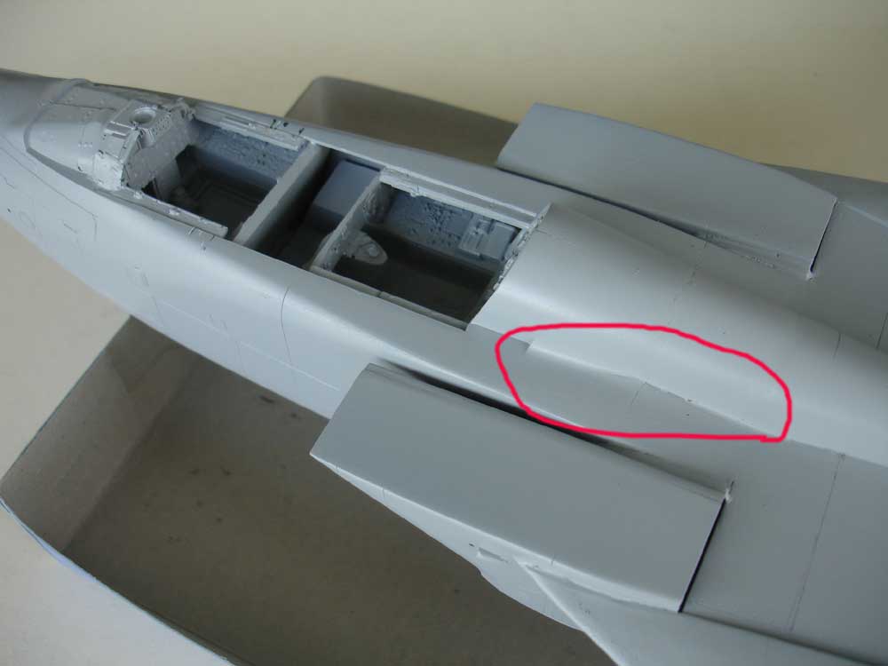
In the red encircled area on the spine some extra putty is needed to get a straight look. But nothing popped up that can not be solved.
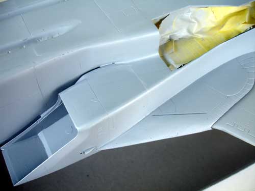
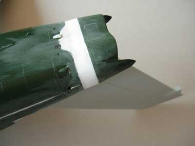
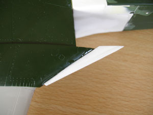
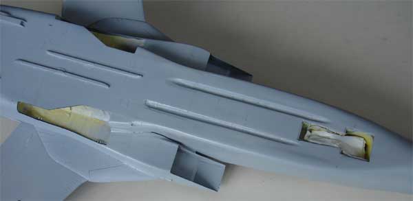
A view of the extended wing
root leading edge
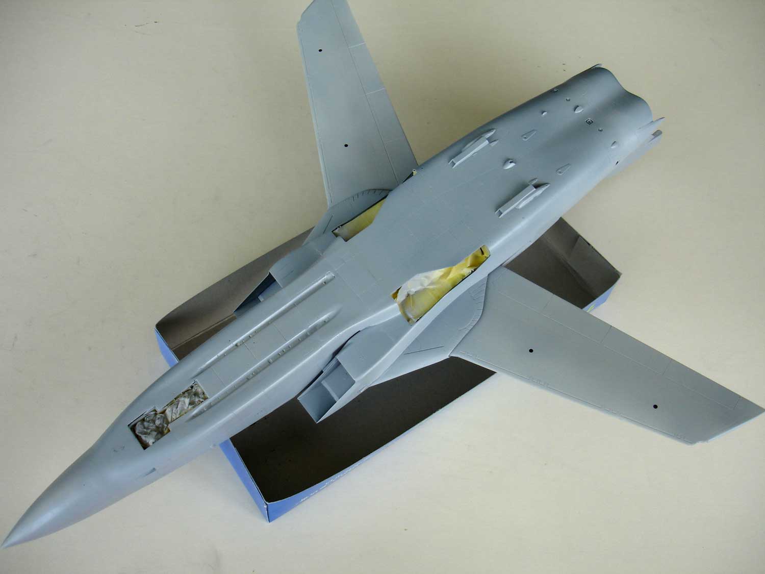
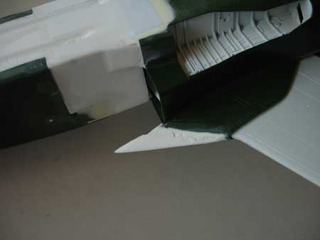
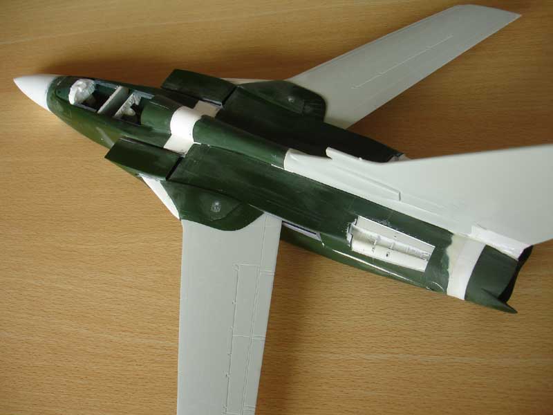
Lower view, note the two forward
missile recesses.
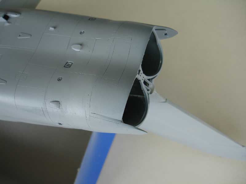
Detail of jet pipe extension
area on the ADV F3
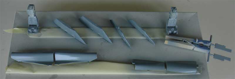
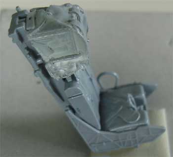
Some other parts also good a first
coat of grey, including the MB seat with new resin head rest/top
OK, did some extra filling in some areas. Here are the results.
The spine is OK now and no additional filling is needed.
 tail
area
tail
area
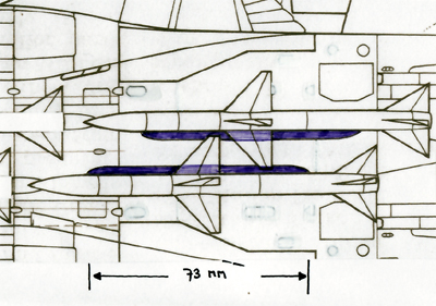
Next to these missiles, long fairings can be seen. These can be made from plastic strip, plastic card and rod sanded in shape (they are too small to mould in resin).
Belly with the aft missile fairings made from strip.
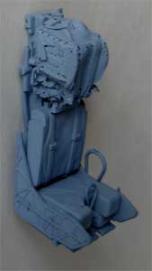
The seat seen in medium grey primer.
Next step is detailling, starting with the cockpit interior.
On to next
[ page 4....]
Back to 1/32 Models.......

(c) Copyright Meindert "designer"/ All rights reserved. Your comments are welcomed by webmaster
Created this page:
July 25, 2008