[ Page 2 ]
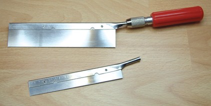
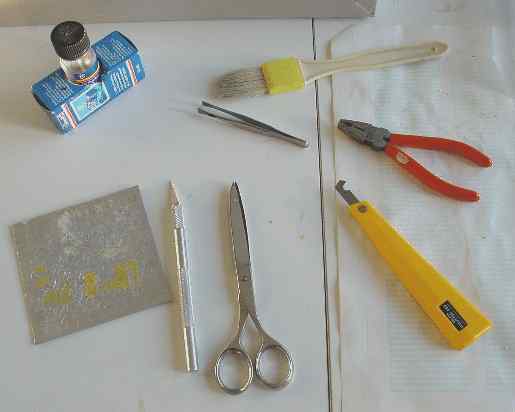
Parts preparation and parts separation needed mainly an X-acto knife to score along the edges to remove moulding stubs. Some minor use was made of a razor saw to saw through some fiberglass enforced parts.
Main resin/fiberglass parts will be glued with 2-component epoxy glue, smaller parts with Lock Tite "thick" superglue.
OK, let go on with the kit.....
STEPs 1 - 16
These steps deal with the seat assembly
and some cockpit panels. Very good parts for the instrument panels are
in the kit, some of pre-painted etched metal and some resin add ons. These
were NOT yet installed at this stage, will be done later after painting
the basic model.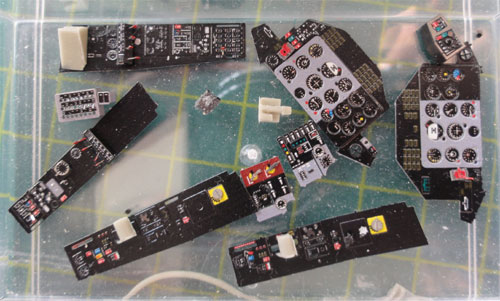
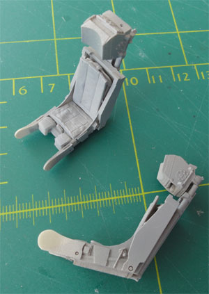
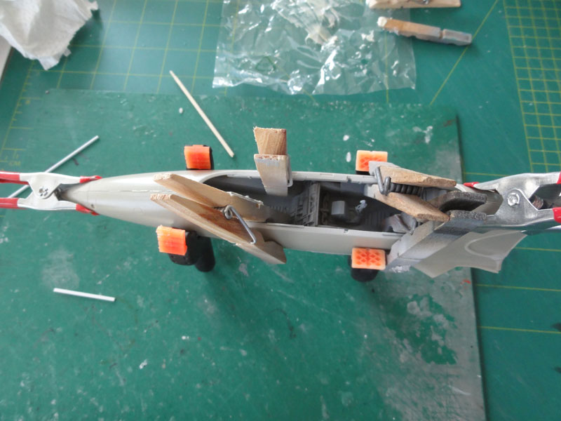
The VS-1 ejection seats designed in Czechoslovakia in the kit are very nice. They come
with a full harness, these are not yet fitted as the seats got first a
grey pimer with the airbrush.
NOTE: Later I found out that the REAR kit seat should be reduced 3 mm in height! So sand away 3 mm from the base of one of the seats, better do this now!
STEPs 23-26
STEP 31
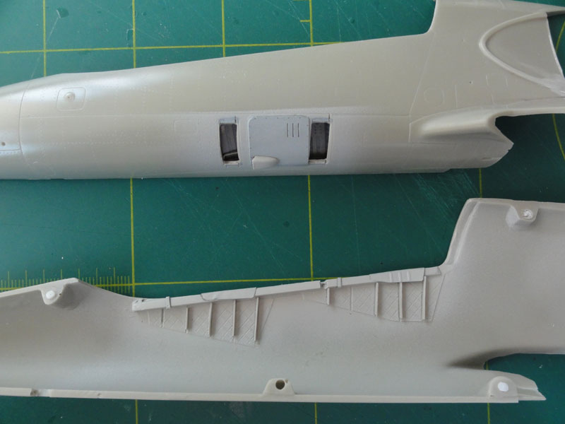
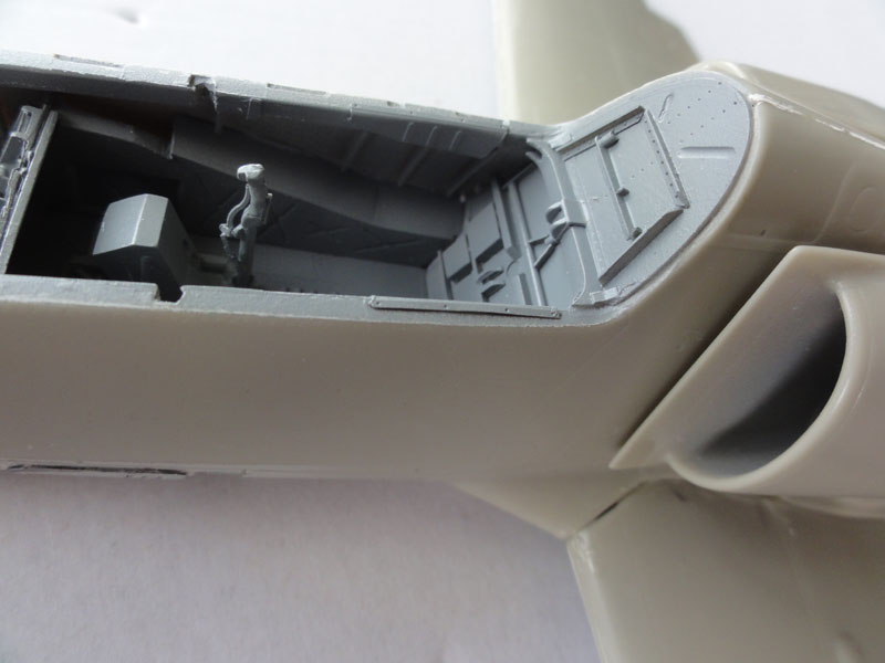
Here also the forward fuselage is
seen. Inside the cockpit, the side wall details were added and a first
coat of grey applied. Note the cut out entry ladder recesses .
Main resin parts gleuing is done with
2 component epoxy glue. This has additional strength on some glue
the larger parts like fuselage and nose halves, wing parts and tails with
expoxy. I used BISON COMBI POWER
Also, I usually use car filler putty.
Here in The Netherlands the white "Alabastine"
auto plamuur is a good choice.
STEPs 37-47
I had some trouble to get the intake
tunnel completely correct, but not a lot is seen later inside. I reduced
the intake tunnel length by 3 mm at the rear of parts 54 and 55. The fan
details of STEP 37 are hardly seen as well.
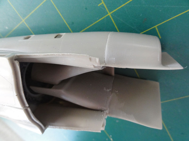
The exhaust pipe fits well and needs
to be inserted as shown per instructions.
STEP 46
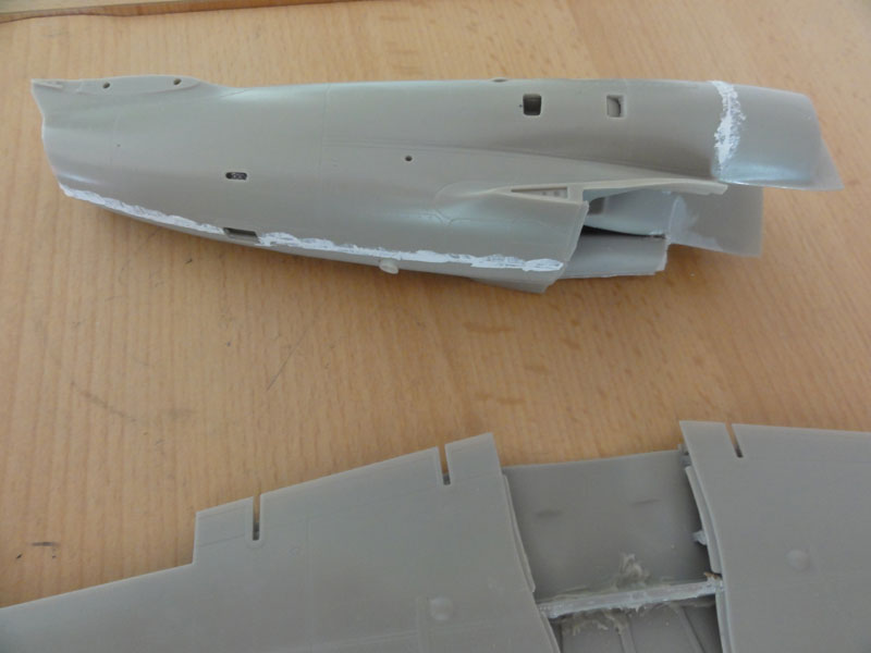
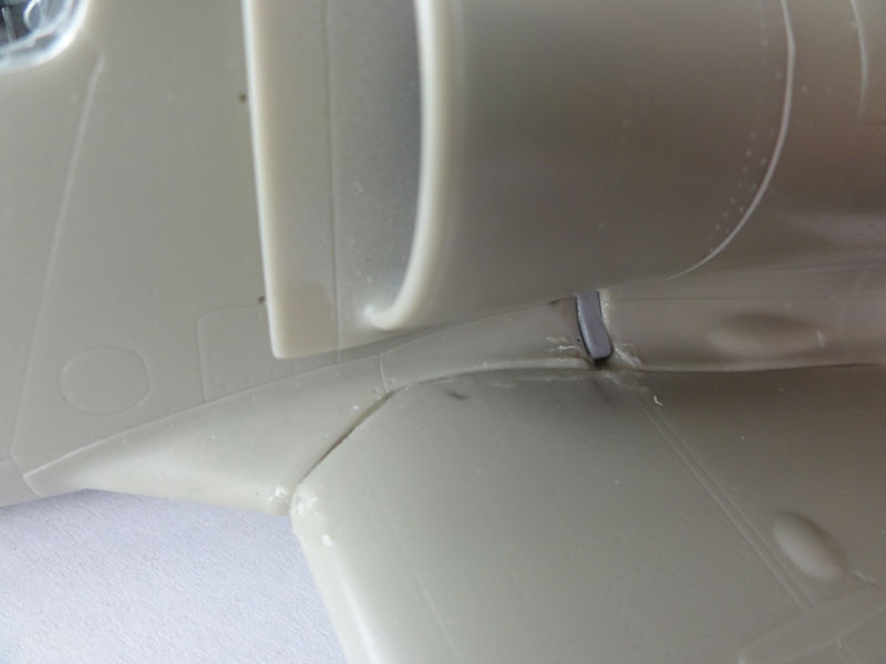
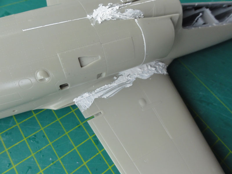
Assembly continued, joining the intake
and rear fuselage first. This will help alignment. The edges between forward
fuselage and intake need sanding and carefull assembly work. The strengthening
rods as seen in STEP 45 are not yet fitted as the forward fuselage is not
yet joined.
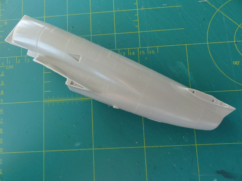
First some car filler (see above)
putty was applied and first sanding done to close gaps. This is better
done at various stages for better handling.
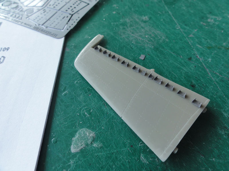
STEPs 47-48
The rear horizontal tailplane is
nicely detailed complete with the air flow vortex generators supplied as
etched metal parts.
I could not find parts 89, they were
overlooked?
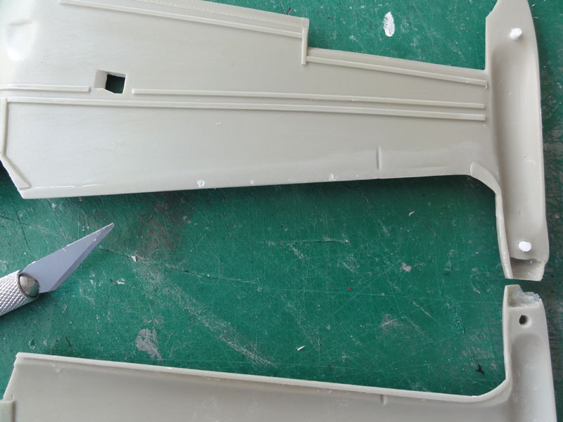
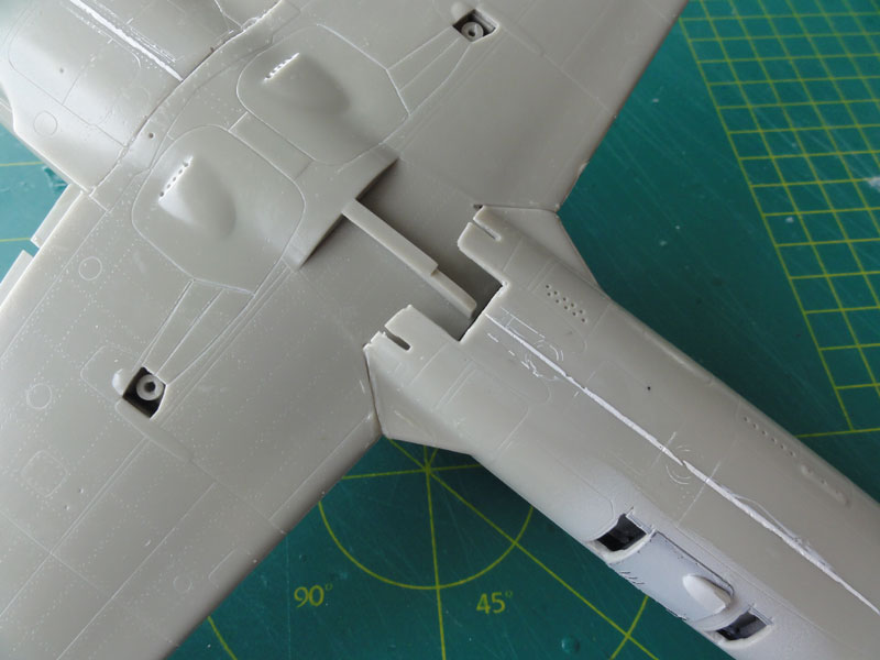
STEPs 52-56
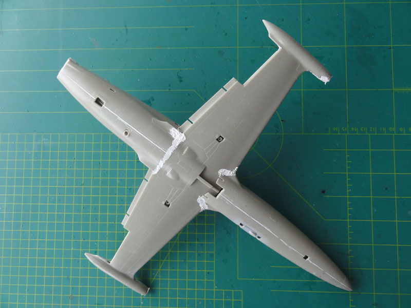
The main wing was also assembled.
The gear bays are not very well seen as the gear bay doors are closed when
a L-39 is parked. And so they are moulded closed in the kit. The door outlines
were inscribed a bit more pronounced with an Olfa P-cutter.
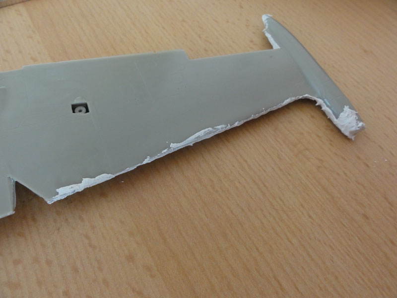
Some putty is needed particularly
at the leading edge, also filling tiny air bubbles in the resin.

The moulding stubs for the resin are seen above and are easily removed by scoring in the edges with an X-acto knife. The stubs will separate from the parts.
NOTE: I found out later that I should have removed the main gear bays doors!! This is NOT shown in the HPH kit instructions in STEP 67! I recommend you do that now at this point. So open up the main gear bay! The main doors are separate kit parts # 67+68.
At the wing tip tanks, lights are
fitted. The moulding showed some fit problems and gaps. Putty is thus the
solution. Particularly at the moulded wing tip pods.
The trailing edge flaps are not yet
fitted at this stage.
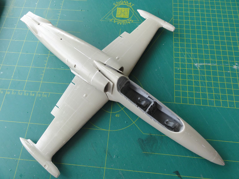
STEPs 32-35
The cockpit tub was now inserted
as well as the provided metal nose weight in the forward fuselage / nose.
The tub itself was not detailed yet
with all cockpit parts at this stage though to prevent damage later on
during further assembly. It got a first dark grey coat of FS34226 using
Gunze Sangyo acrylic H335 as well as the instrument covers and bulkheads.

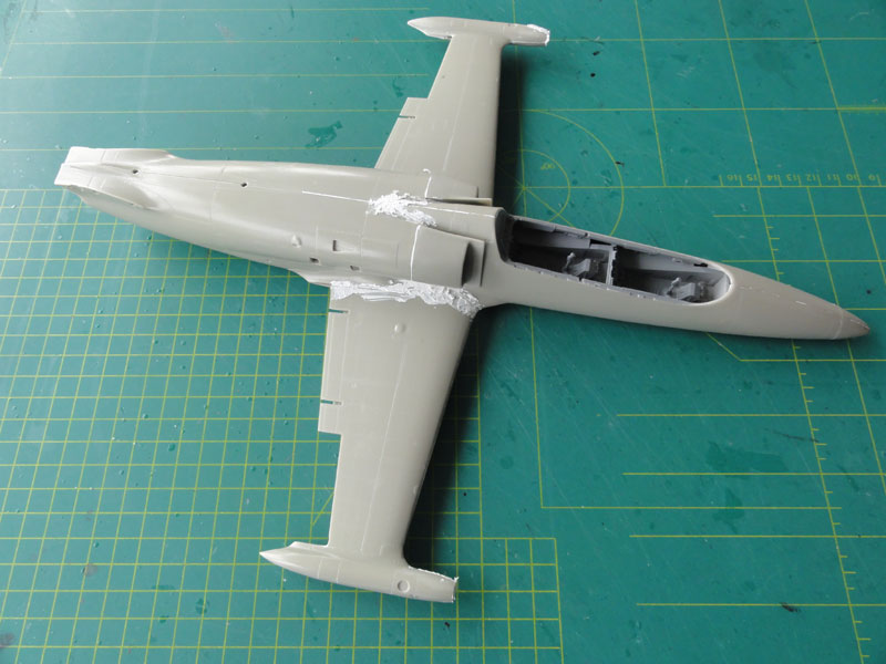
The joining of the forward and rear
fuselage was not easy. The assembly needs a lot of carefull alignment work
with not much room to manoeuvrer.
A gap needs to be filled as well
with card and putty in an awkward place. But it can be done.
Car body Filler / putty was applied
and after drying sanded.
The fitting of the strengthening
rods is very carefull work. I cut metal rods from a paperclip. The correct
location is seen in the insides of the intake lips. Use super glue.

The main fuselage and wing is now
ready for further kit assembly.
..

(c) Copyright Meindert "designer"/ All rights reserved. Your comments are welcomed by webmaster
Created this page
May 8, 2014
Updated June 16