[ page 1 ]
1/32 scale model of Kitty Hawk for the OV-10 Bronco by Meindert de Vreeze
 ..
..
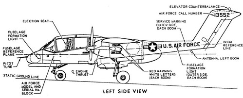
The Bronco was developed by North American as there was a need for a light attack and observation aircraft. Several versions were developed. I saw the Bronco at various European air shows of the USAFE in the 1970s and always liked the aircraft. Now it is here in 1/32!
See more info on my "real" Bronco aircraft page here....
page 2
real bronco

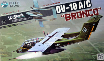
Kitty Hawk from China released a splendid injection moulded kit in 1/32 scale of the OV-10D (kit KH32003) in 2014. In 2016 this kit of the OV-10A / C was released (kit KH32004).
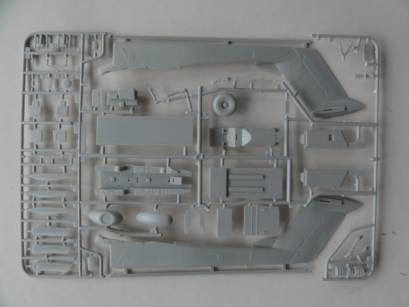
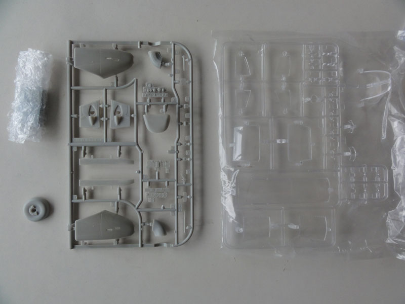
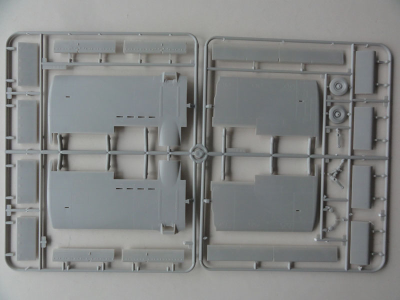
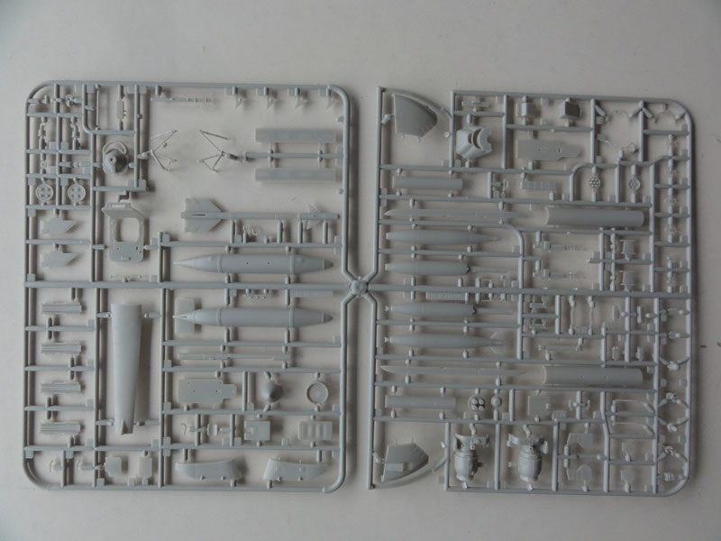
The kit has over 200 parts in light grey medium soft plastic with 11 sprues, a clear sprue with transparant parts for the plexiglas panels in a sturdy box and an etched metal set and even a metal ballast weight.
The instructions are nicely done but during construction I found some errors in part numbers or missing part numbers. Sometimes you really need to search for the tiny parts. The colour schemes are shown in full colour though I think some paint colour suggestions are not correct.
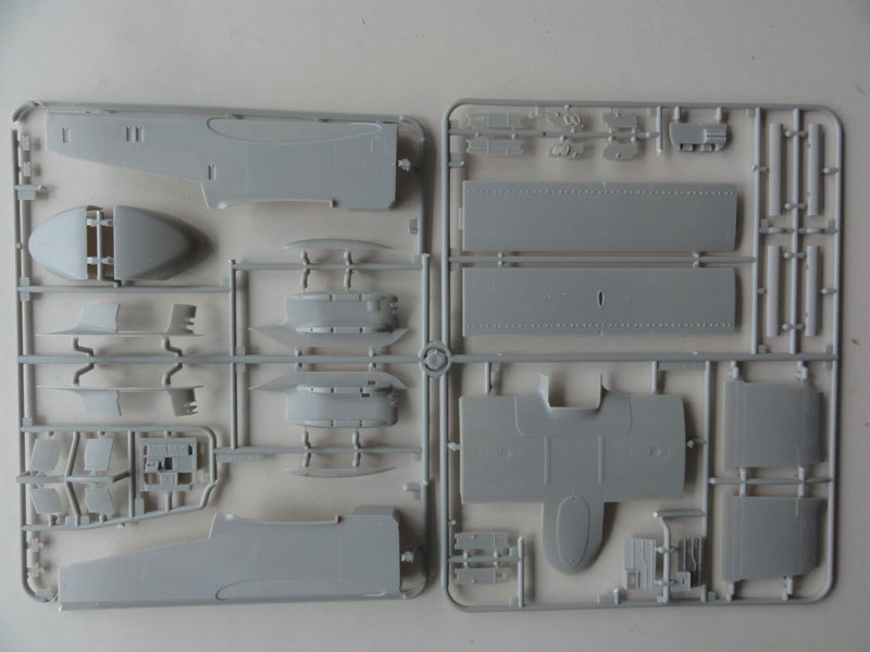
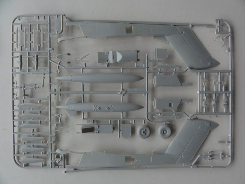
Below left here is sprue "A" that has the specific parts for the OV-10A / C such as the standard shorter nose (the rest seems to be common parts as also seen in the OV-10D kit).
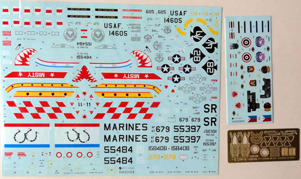
There is a very nice decal sheet with decals for 6 schemes:
- OV-10A, US MARINES CORPS of VMO-5 in green -grey scheme
- OV-10A, USAF 549 TASG in overall grey
- OV-10A, USAF 20 TASS "Misty" in overal European Green scheme
- OV-10A, US MARINES CORPS, VMO-2 in green-grey
- OV-10C, Thai Air Force in green-brown-grey scheme
- OV-10A, Philippine AF in medium grey-green-light grey :
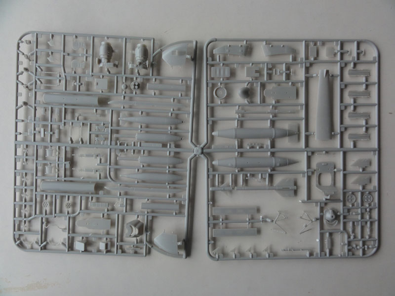
The kit has positionable flaps and surfaces and separate spoilers. The large canopy plexiglass doors can be set open and 2 detailed Garrett T76 engines are provided with pretty good detail overall. The compartment tailcone can be set open.
There is also a large selection of stores (including AIM-9B or -9L Sidewinders) though I am not sure if the parts are accurate. The early OV-10A could fire the AIM-9B but I am not sure about the later AIM-9L. The large Bronco fuel tanks are also nicely provided in the kit.
Overall the kit is very nice with lots of detail.
This kit will be made as a OV-10E of the Venezuelan Air Force (FAV), which got a dozen in the 1970s, from this kit with aftermarket decals. The OV-10E is very similar to the OV-10A. This model will be a nice companion to my other 1/32 FAV models like the F-16A and T-2D Buckeye.

As with many kits, the assembly order suggested by the kit instructions are better not followed. Major assemblies are better done first before adding any smaller detail parts. This 1/32 Bronco kit has the large wing in different sections that will need careful alignment and strong joints. A spar is really essential so some improvising is needed.
The kit parts have quite some injector pin marks but after installment many of those can not or hardly be seen. The most noticeable that need filling is in the cockpit side walls. These can be filled with TIPP-EX fluid in stead of filler.
STEP 1
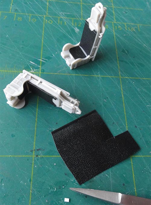
The LW-3B ejection seats in the kit look fine but are somewhat inaccurate. Seats are asymmetric in real Bronco's with the parapack left or right on each seat. Always 2 different seats configurations are installed, this will ensure that when ejection is needed the seats eject out a bit asymmetric and do not collide.
So one parapack container part #I18 should be positioned on the port left side. I also had a gap between the rear frame H27 and the seat back I4 so added a piece of card. I also added a bit more detail on the seats like a handle at the port side next to the head rest and the missing ejection handle in front. In the shape on top of each seat, the "canopy breaker", a hole was made.
On the seat I added sort of leather cloth I had to suggest the seat cushions.
Kitty Hawk provides etch metal seat harnesses, these will be set in place later.
STEP 2
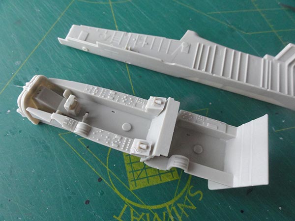
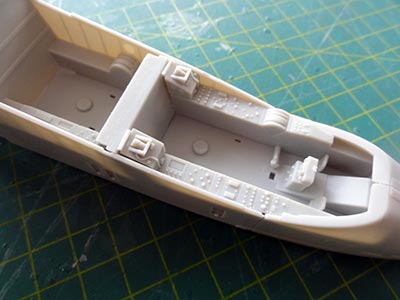
The cockpit tub was simply assembled. Do not forget the provided ballast weight, I added some more weight just to make sure and hope that it will be enough. (I found out later EXTRA weight is also better to install).
I had to close some gaps between the rear and forward section. The large moulded floor stubs will later be hidden by the seats.
The instrument panels look good with raised details but are a bit inaccurate. Decals are also provided for the instruments and these can be added on top of the raised details with strong decal solvent later on. A first glance showed that the pilots' forward panel on the OV-10A does not show an instrument at the left section, this area often had a UHF comm panel (see instrument referred to as no 44 on the detail page here....). Also, the rear panel for the observer looks quite a bit different as in the kit. These changes will be done later on to the panels as they are installed at a much later stage.
STEP 3
The seats are obviously not yet installed at this stage.
The nose wheel needed filler to close the gaps between left and right halves. The gear was detailed a bit with a hydraulic line but not yet set in place. Inside the bay more will be added later on.
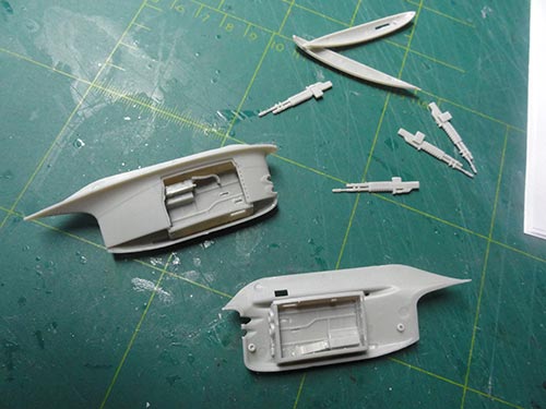
STEP 4
The avionics equipment rack may vary a bit between versions of the Bronco. I opted to net yet install these parts yet, only the roof part #F18.
The kit also has parts for the utility compartment aft of the cockpit. A floor and roof is provided but no further interior details. So if you want for example a MEDEVAC you will need to make the stretchers etc by scrap.
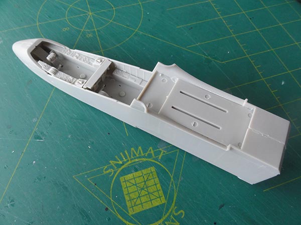
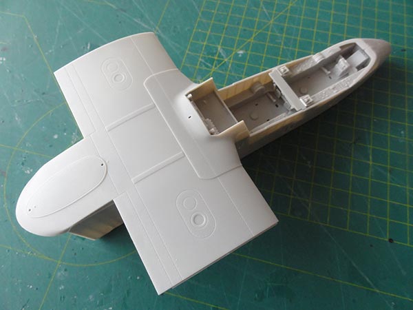
The forward fuselage can now be assembled as shown in the kit with the shorter OV-10A / C nose. The fit is remarkably good after cleaning up the mating surfaces. There are some small gaps that can need a bit filler / putty.
For this OV-10E (OV-10A) I did not use the nose bits #A16, A17 as seen in assembly STEP 6. Also do not install the (retracted) LADDER, parts #F38+F44 seen in STEP 8.
I now first moved to...
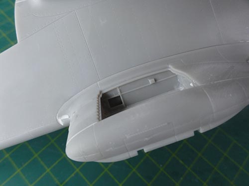
STEP 7
The fuselage stubs were assembled to check their fit, this proved to be excellent. I opted to keep open the starboard right gun ammo panels.
NOTE that the 7.62mm M60C guns types and configurations may vary on Bronco's. Often these guns were not installed, so check which particular Bronco model you want.
Below the stubs are hardpoint to carry for example 2.75" rocket launchers.
STEP 8
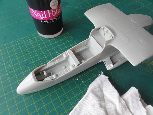
The stubs were set in place and only very tiny amounts of putty were needed. After drying, the putty was removed with a cloth with nail polish remover. This avoids sanding and is quick.
I also joined the rear tail cone halves. Though not decided if this single cone will be set opened up swivelled to port I detailed the avionics rack #D11 inside nevertheless.
The other part installments in this STEP were not yet done.
STEP 5
Here it is much better to first install the upper wing mid section #E14 on top of the fuselage and NOT yet the lower wing parts #E19 and #E20.
To add strength, I added a spar. This is simple a piece of flat wood. Was fixed in place and after curing, the lower wing parts were set in place. The spar was glued with Bisonkit, use only tiny amounts here as it "eats plastic".
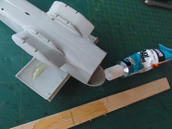
The spar was clamped in place and set to dry.
The flap parts were also assembled but not yet set in place, leave for much later.
Meanwhile I moved to...
STEP 11
The engines and structures are provided as detailed parts. The cowling doors can be set open and shown detail inside.
(Note that even when you set the cowling doors closed you will need to assemble the main engine parts to have a propeller fixation point).
The GARRETT T76 parts like fine. (for a drawing look here at the detail page). There are even etched metal screens in the kit though the rear exhaust one is not seen later on.
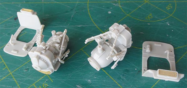
Do not yet install the engines to the bulkheads, leave that for later to avoid damage.
As still the wing-fuselage is drying, I moved to...
STEPs 12 + 19
The main gear legs and wheels were assembled. Use clamps to get strong joints between the gear leg parts.
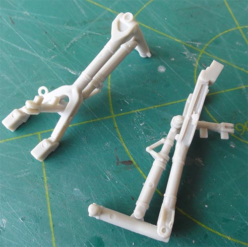
I added a few hydraulic lines from thin electricity wire.
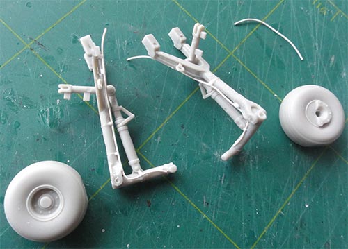
Do not yet fix the wheels nor the legs to the model gear bays.
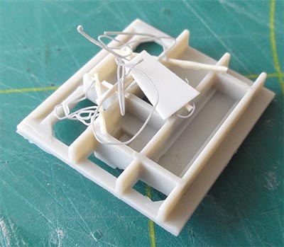
STEPs 13 + 20
The main gear bays were simply assembled. There are a few ejector pin marks, these were filled (e.g with TIPP-EX). Do not set yet the main gears in the bays.
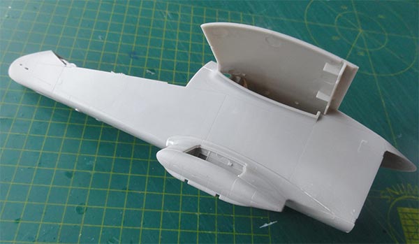
STEPs 14, 15, 21, 22
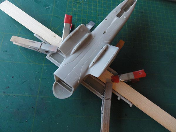
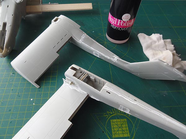
The large typical Bronco tail booms were now assembled. The parts #F40 and #F42 appear to be avionics bay doors so do not need to be completely invisible. The main gear bays were set inside but NOT YET the upper cowling parts #I2. The engine bay fire bulkheads were set in place but without the engine assemblies.
The fit is pretty good with only tiny amounts of car filler / putty needed. Nail polish remover with a cloth was again used to remove filler in stead of sanding. This is easier and quick.
STEPs 18, 25
The outher wing sections were also fixed on the tail boom assemblies. This helps with getting strong joints and these sub-assemblies wil be joined with the center fuselage-wing later on.
Note that the ailerons and flaps are not yet installed.
On to next [ Page 2.... ]
see here...
(c) Copyright "designer"/ All rights reserved. Your comments are welcomed by webmaster
Created this page
December 28, 2017