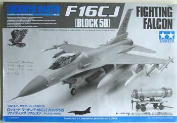
Lockheed Martin F-16C Block 50
Fighting Falcon
[ Page T-1 ]
to Page T3..
F-16C "late Block 50" using the Tamiya kit
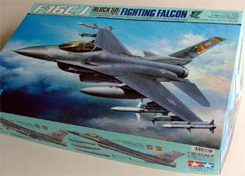
The Tamiya
kit of the F-16C is impressive as seen on this page
with details. (this page compares it to other 1/32 F-16 kits).
The Tamiya kit
will be used to model a F-16C Block 50 as provided by the parts in the
kit. It will also be improved in some areas, especially at the lower aft
fuselage area at the engine (but more on that later on).
Also for that
reason, the engine bay will be closed with no detailing inside the engine
bay. The engine will be made as a separate model to be placed on its supplied
dolly. Also, it was decided to close the gun bay and the ammo drum bay.
Alternatively, you can set these open with the nice detailed goodies you
get with this kit.
The Tamiya steps as indicated in the instructions are not followed in that order. In this modelling Report, a more logical order is followed...
so let's start
!
 34 MB
34 MB ![]()
DOWNLOAD INSTRUCTIONS: use right
mouse / click download
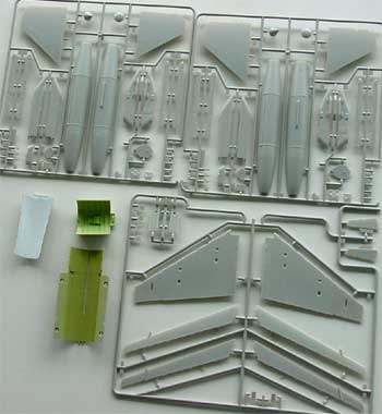
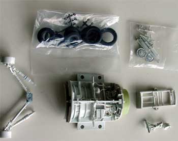
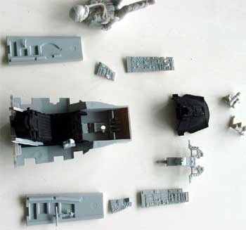
Begin first
by making small sub-assemblies and than "pre-painting" smaller parts. This
will take quite some work as there are many parts in this nice Tamiya kit.
Some airbrushing I do with parts still in the sprues as seen here.
Also Eduard
etched metal set # 32-128 was used for the kit, although you do not really
need it as the kit has very good detailing.
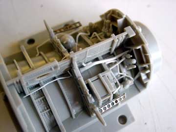
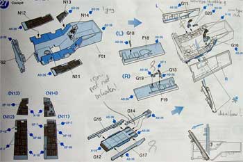
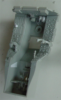
Step 13: Main gear bay
Assemble as shown, there are lots of details here. You can add hydraulic pipes from stretched sprue. I also added some parts from the Eduard details set
(The engine bulkhead parts are not applied to this kit and will go to the spares box as it was decided to assemble the engine bay closed).
Step 16 is not
required for this model.
It is recommended to fix the heat pipe #C17 only at the bottom, keep free to move in the upper area on D4
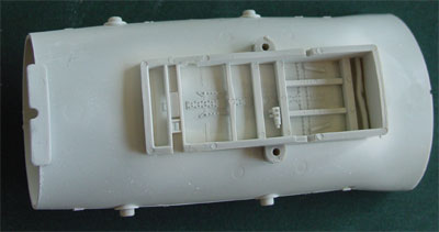
Steps 20, 21 with intake scoops were assembled as shown.
Some putty
was needed here.
Do NOT yet do
step 22, skip this one!
Step 23 with the main gear legs were assembled as shown. I left off the tires obviously. Some detail painting will be done later on.
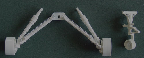
The whole assembly
of nose and main gear, and bays was sprayed white and detailed with some
extra sprue and rod and details added with various colours.
Before continueing.......
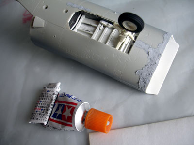
Aft fuselage
section improvement
The Tamiya
kit has an inaccurate aft lower fuselage section at the engine area. It
seems that Tamiya had to make a compromise in here as the engine provided
is "removable" from the model. Compared to actual pictures and the Academy
and Hasegawa models, the cross section is not curved enough, but a bit
to much squared, especially at the ventral fin area and at Tamiya part
# B20.
Also, it was decided to try to make the provided Tamiya engine stand as a model on its own. This required to do some changes on the exhaust pipe assembly for the separate engine. I will use spare parts from the various kits.
So, after this work, the overall look of the F-16 will be improved in the rear end area.
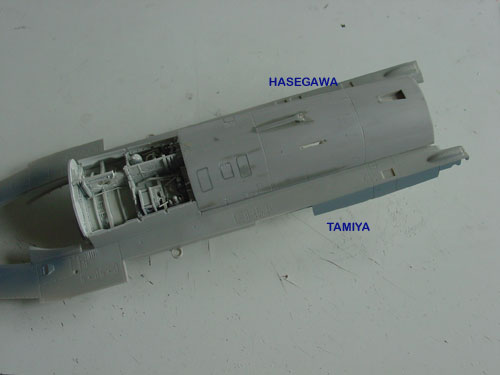
As I got from a Hasegawa F-16 kit the aft lower fuselage (part #A2) from the spares box of Peter, it was possible to replace the incorrect lower Tamiya section. When checking the dimensions of the lower aft fuselage section, it turned out that the width was exactly identical between the Tamiya and Hasegawa kit (and by the way also identical to the Academy kit). The length was also nearly the same.
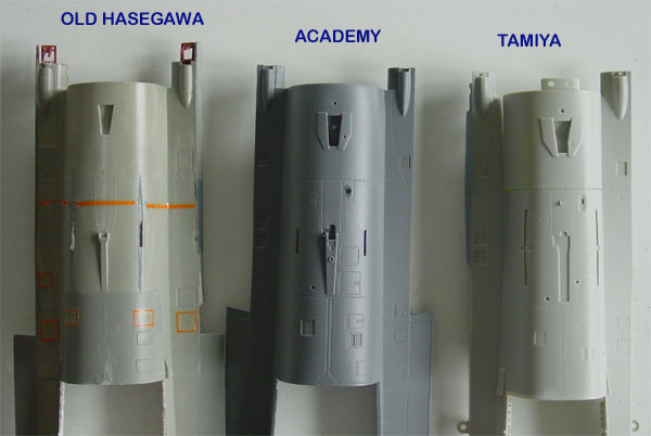
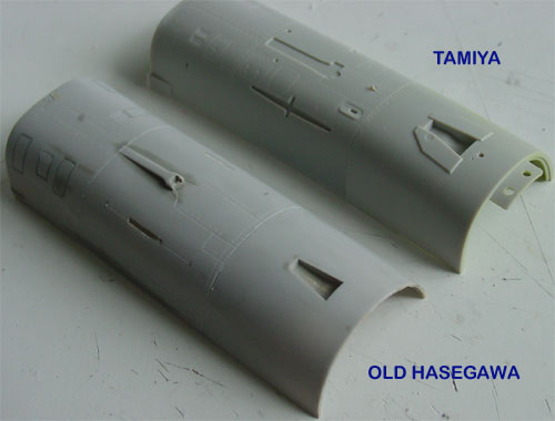
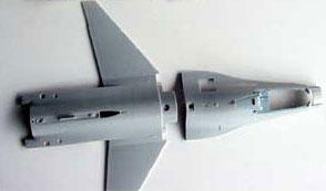
Aft lower fuselage section comparison
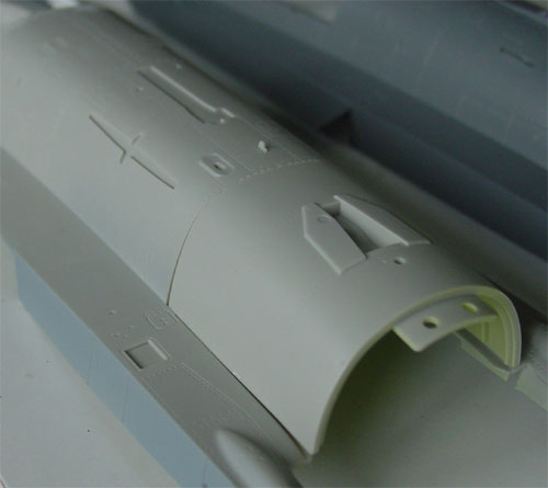
Tamiya aft
section, a bit to squared, as seen below when comparing the exhaust pipe
fairings.... it should be a circle.
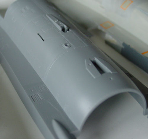
Compare also
to the correct aft Academy kit rear section seen here
First, from
the Hasegawa spare part #A2 the aft section was sawn out with a razor saw.
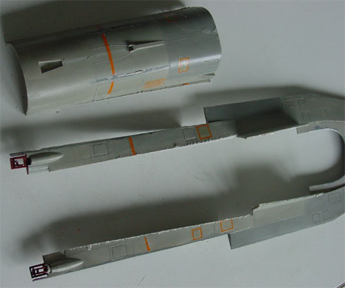
The cut out
part was sanded and cleaned up. Panel lines were inscribed in the new part
from Hasegawa.
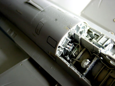
Here another
comparison can be seen.
In order to reach the correct total length it was also needed to saw off 1,5 mm section at the rear of Tamiya part # A1. Later on, the exact correct length will be achieved by adjusting the exhaust fuselage fairing.
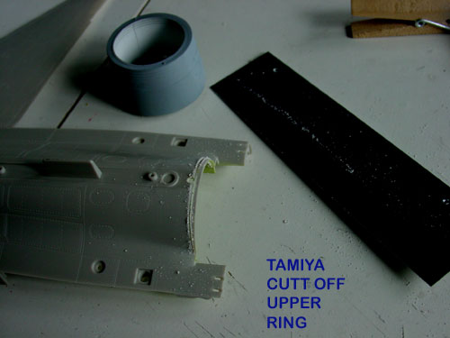
The merged parts
together. Make sure to tape on the upper fuselage section #A1 to make sure
the width is correct. The lower and upper fuselage section dry fitted and
matched perfectly.
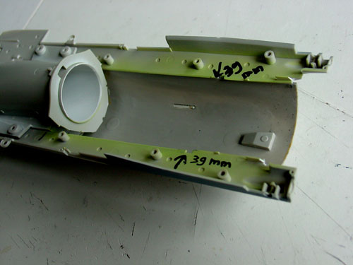
Also, you will
see that the main gear bay will fit perfectly, only some moulded small
locator strips had to be removed inside the Hasegawa part.
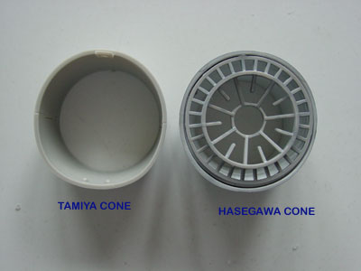
For the fit
of a Hasegawa rear cone (part # J3), it was needed to remove 2 mm plastic
in each corner. Now, the Hasegawa cone wil fit OK.
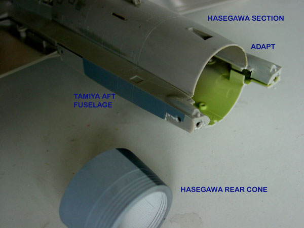
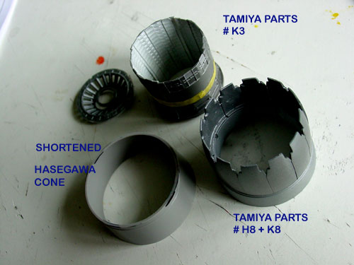
Next task was the work on the engine exhaust area. For the later "C" types, and also F-16C Block 50, the GE F110 is installed on the real plane. Tamiya provides a separate removable engine with a dolly, but unfortunately only parts for one exhaust pipe. (You are supposed to exchange this exhaust between either model or engine).
The Tamiya exhaust pipe looks very nice, so in order to use this on the F-16C model, it was decided to put these on the model; on the other hand it was decided to craft the spare Hasegawa F110 exhaust parts onto the engine itself, it would than be a model on its own (more on that later on).
Note that the
Hasegawa part #J3 will be used to get a perfect fit to the aft fuselage
area itself. In order to fit the exhaust pedals of the Tamiya kit, it was
decided to use Tamiya part # H7.
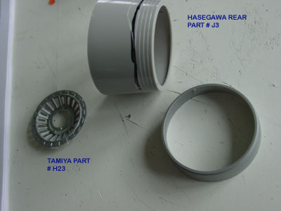
It makes it
possible to craft both parts together and to get the correct length; it
was needed to cut off 7 mm (0,3 inch) from the rear of the
Hasegawa part #J3. This was done a razor saw and after some sanding, a
good fit is achieved. Some putty may be needed here to get a very clean
merge.
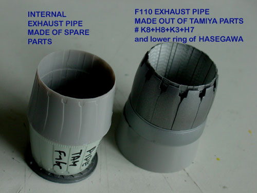
The Tamiya exhaust was assembled using the Tamiya parts #K8 and H8 as shown in step 11 of the instructions. It will fit perfectly onto part #H7
The ENGINE is a model on its own and the assembly can be seen here......
The inner exhaust
pipe was created by not using parts # K3 on the separate engine, but to
set them into the exhaust itself. Also, the pipe would be given extra
depth by using some spare parts. (In this case an old Revell pipe and a
spare engine burning section , parts # E6 + E20 from the Academy kit;
you can also search for your own parts in your spares box).
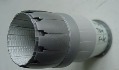
The overall
assembly of rear external exhaust and internal exhaust pipe. The exhaust
area and lower fuselage area for the Tamiya model are now perfect.
In step 24 and 25, as noted the rear of the lower fuselage was replaced. The main gear and arrestor hook parts were not installed, but the bulkhead # F12 and smaller details were added. The ventral fins #B18+B19 needed some sanding at their base to get the good position fit to the new belly and their notches were cut off.
Step 26 : I
added the flare dispensers, metal parts 'b1"; use what you need for your
particular F-16C.
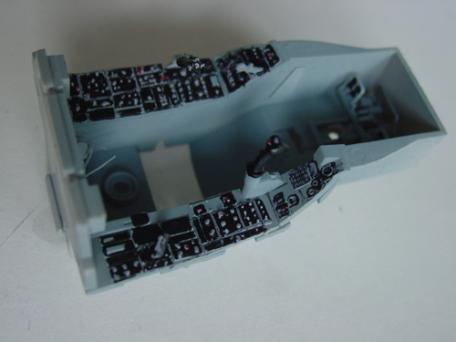
Step 27: cockpit area
The Tamiya kit
has very nice parts for the cockpit, with raised details on the instruments
and so on. The Eduard etched metal set does not provide any improvement
here as etched metal plates are simply nor "3 dimensional".
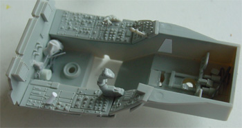
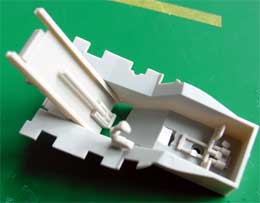
Here you see
the basic frame for the Tamiya tub, to which details are to be added. I
did not like the "option to keep items removable", such as the seat etc.
From parts #G15 and G17 the notches were removed. I also cutt off 10 mm
from part # G14.
 .
. 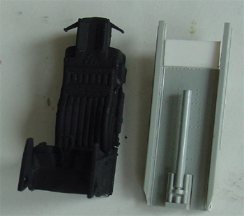 seat sprayed black
with its rear rail plate
seat sprayed black
with its rear rail plate
First, some
piping and details were added at the rear bulkhead aft of the tilted ACES
II seat and in the pedals as shown in step 31.
At the cabin
walls, also some extra detailling was added from rod and card.
 .
.
In the cockpit,
some etched metal parts were used from the EDUARD cockpit set # 32052.
The instruments
and side panels got a first coat of medium grey. Details were painted satin
black. After drying time, details were inscribed with a sharp needle suggesting
instruction texts etc. The instrument knobs were painted light grey with
a toothpick. Some details were set-out with red, yellow and white again
with a toothpick.
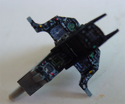
The instrument panel
was painted and detailed. Some weathering will also be done with some light
washes of darker grey in the cockpit.
Step 29:
The Tamiya parts for the ACES II ejection seat are fine and were assembled as shown. Check out part #G9 as not all seats used on the F-16C's have the sensors. The seat can be detailed also using parts of the Eduard set.
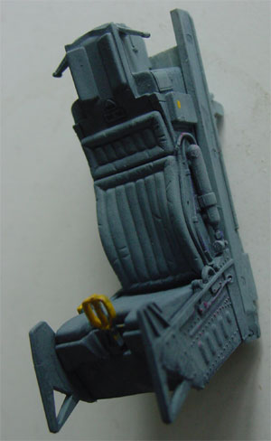
In step 30, the pilot was obviously not (yet) installed. Final finishing and adding metal and cotton seat harnesses as shown in step 29 to be done later on.
Step 31 was not needed for closed ammo bay, except for the pedals .
![]()
Skip step 32
for later.
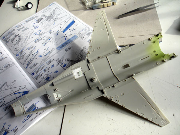
Steps 33-34: assemble the main parts as shown. It is a perfect fit! (I hope that Tamiya will come with a two seater F-16 in the future, as the separate part #B28 seems to suggest....). Please note that there is also a spare part #B17 not mentioned in the instructions, which is useful for some F-16 types, such as the MLU for example.
NOTE: early
F-16's before and up to block 30 have at the slat at the inboard position
only "2" slat rotating fingers". Later block beyond block 30 F-16 have
there "3" fingers. Probably this is modification applied later to cope
with more stress.
The old Hasegawa
kits have indeed "2 fingers" which is correct for the earlier F-16's. This
Tamiya later block 50 F-16C has the "3 finger" style inboard slat rotating
fingers" which is indeed correct.
As the gun area
was not to be displayed, these parts were assembled closed. It is recommended
to fit gun tunnel part F44 and the panel door parts B6, B13 at this stage
for better handling.

(c) Copyright "designer"/ All rights reserved. Your comments are welcomed by webmaster
Created this page May 21, 2006