Dutch naval air service
[ page 2 ]
Conversion of Lynx model in 1/32 scale of Revell (Mk.88A, kit ref no 04652)
... continued from page 1....
![]()
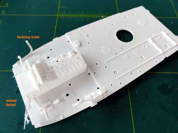
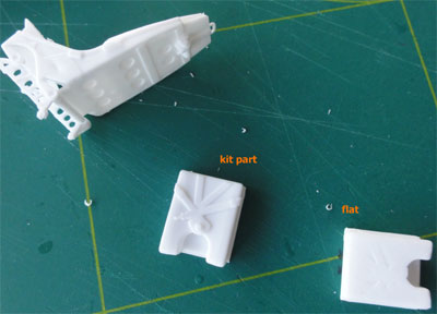
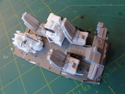
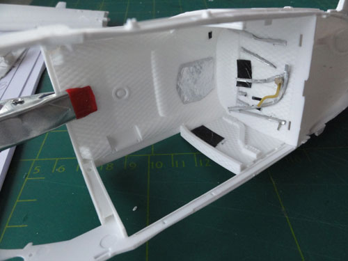
OK, with 4 new parts, let's continue
the build of the Dutch Lynx SH-14D model.
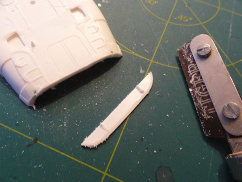
The bulkhead areas were removed with
the razor saw.
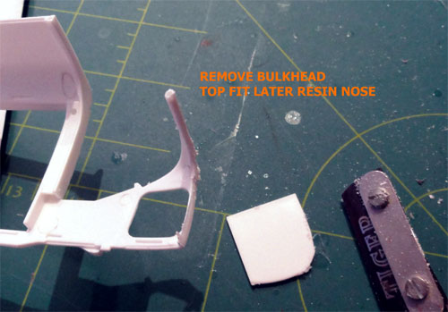
.
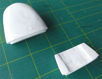
The two resin nose parts were joined,
and gaps and tiny air holes filled. Set aside for later fit.
 ..
..
![]()
STEP 1
Open up the holes in the floor as
indicated in the kit instructions, depending if you want to have the sonar
installation inside.
STEPS 2- 4
The interior is next. The Dutch Lynxes
have some variations, depending on the version. The bar on top of part
#83 was cut off.
To fit the resin nose later on, a
bout 5 mm was removed at the front of the console parts #81, 82 to get
some room for adjustment later on.
Some small wire details were added
at the central pedestral.
STEP 5
The
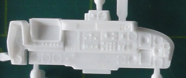
main instrument panel of the Dutch SH-14D has not the large display as
the German mk.88A and a different layout, seen here (courtesy www.ipms.nl
) :
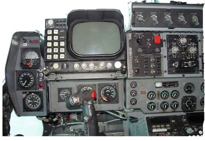
SH-14D
left panel area and a drawing:
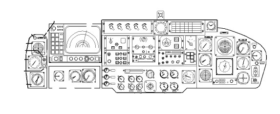
We are lucky, an extra part is in
the kit! We can use part #266A instrument
panel and its backing part (not #148) in the kit, although it is not indicated
in the instructions!
Half of the upper instruments were remove. Behind the panel a coaming was added from card that will close a bit the gap between windscreen and instrumentpanel. Wth rod and sprue some were added as well.
With painting,
the various instrument panels were suggested. Of the kit decalsheet, the
clockwork was punched out with a Punch and Dy set and applied each clock
decal.
 .
.
With Micro Kristal clear, each instrument
clocks got a drop, the white subtance still drying as seen below..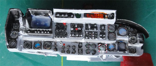
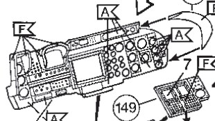
On the console mid-panel #150, the
raised "knob" at the end was cut off. Replace instrument part #149 by kit
part #234 for the SH-14D.
STEPS 6-8
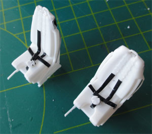
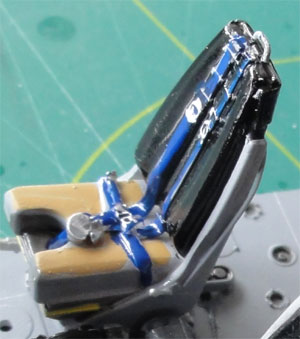
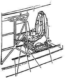
The seats are well detailed in the
kit and their backs look great.
The fire extinguisher was slightly
repositioned. The first add boxes were made from metal foil. The leather
seat covers were made from bended foil as well. At the pilot seat, the
fairings at the back were adapted and wires added as well. Parts used were
#73, 74 (parts 152 were not needed)
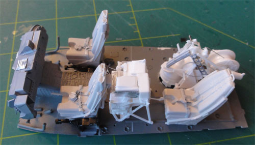
The seat belts moulded on the seat
cushion parts #71 were sanded flat, new belts to be added from foil, wire
and spare etched metal bucklings and clips.
 ..
..
The sonar operator seat was not forgotten.
STEP 9
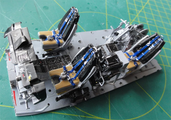
The seats were not yet installed
on the floor, first they will be painted / airbrushed various greys.
From winebottle sealing, straps and
belts were cut and painted. Buckle locks were obtained from etched metal
Eduard parts found in the spares box. Next several paints were applied
with variuous colours. Note that it may vary depending on the particular
Lynx. The lifevest is seen here as yellow coloured. Also note the sheepwool
cover.
STEPS 30-31
The sonar operator seat is fine and
was simply assembled and detailed as the other crew seats (see above).
STEP 10
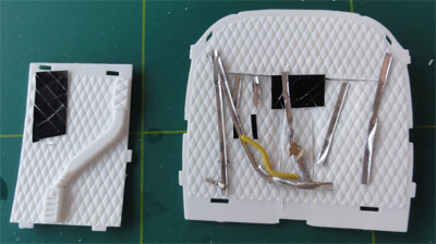
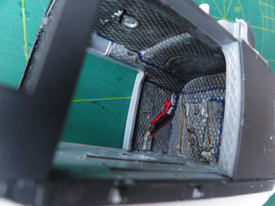
The interior cabin roof is fine,
the rear bulkhead and side walls got some additional "webbing" detail form
card. Some insurgions were made with a razorblade to get some additional
depth. With white glue details were added as well. Note that all the time
real Lynx pictures from a Walkaround were used.
 ..
..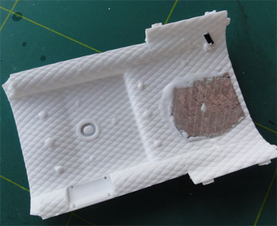
The sidewalls were NOT set onto the floor, but were joined among themselves. The floor will be positioned much later, after painting.
NOTE: the winch is also in the kit, parts # 274, 270, 271, 276 I believe. It is not indicated in the instructions. Not yet assembled.
STEP 11
It was decided
not the fit the rear seat bench #94A+B. The sonar will be set in place.
STEPS 12-22
These steps are OPTIONAL, only needed
if you want a sonar inside the model cabin.
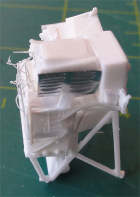
The dip sonar system and its operator station will be set into this model. The Dutch system looks quite different as in the kit, but parts of the rack can be used. With card, rod and by cutting some of the kit parts (#163, 165, 171) the boxes could be re-used.
 .
.
and after painting..... and drybrushing
STEPS 23-29
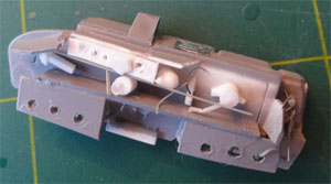
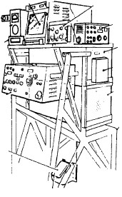
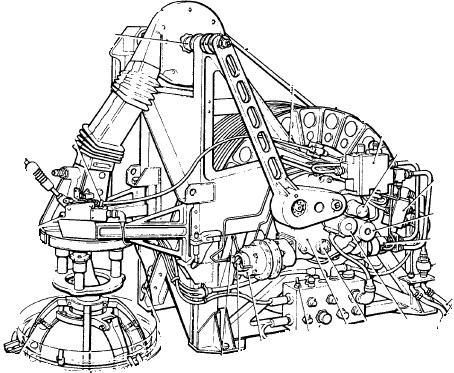
The sonar installation itself is
in the kit and with its motor well detailed. The Dutch sonar installation
is however quite different. Looking at photos of the IPMS Walkaround,
with sprue, rod and card remodelling and scratch work was done.
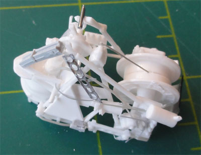
This took a whole afternoon to make,
including the sonar operator station as described above. Some kit parts
could be used after adjustment.
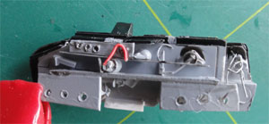
 .
.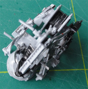
Painting was done with various colours
of grey, black and others.
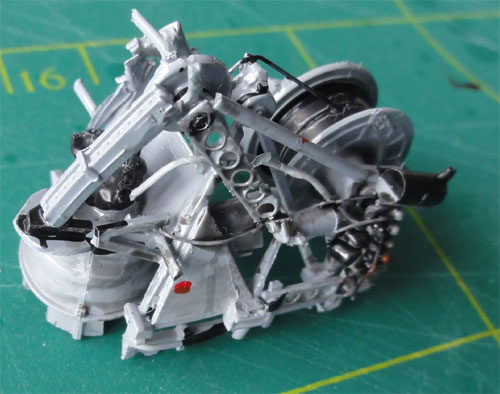
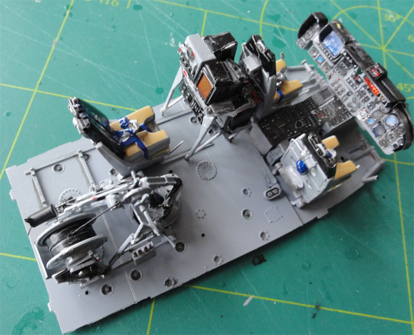
STEP 32
Do not yet fit the sonar equipment.
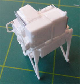
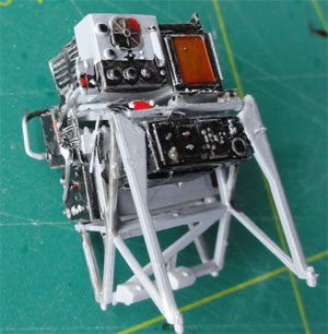
Here the several sub-assemblies are
set on the floor, but not yet glued to get an impression of the nice interior:
.
and painted....
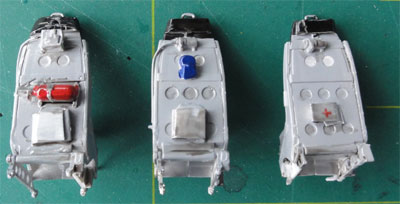
The basic grey colour used was about
FS36270 (Gunze Sanyo #306) but also FS36320, FS35237 (Gunze #307, #337).
Instrument panels black with details in red, yellow, white. Simply sand
off the paint from the raised switches and knobs will reveal the detail.
.
STEPS 33-34
Fit interior frames and so on. These
are excellent fits and no problems whats so ever.
Now, before proceeding further, all interior parts and the inner sides of the fuselage halves, floor and cabin roof got a base colour coat of various grey acrylics colours applied with the fine airbrush. The other colour details were handpainted with the brush.
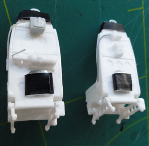
STEPS 35-37
The two fuselage halves were joined,
but the floor not yet fitted. The joined sidewalls were inserted. They
will be sprayed with the interior various grey colour.
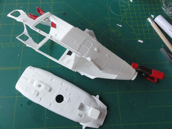
The fuselage insides and floor got
a coat of FS 36320 (Gunze Sanyo #307) . Note also the various details made
from stretched sprue and rod.
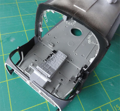
Of the assembly that deals with the main rotor gearbox and mast not a lot will be visible. So these parts can simply made as per instructions. The large part #5 was NOT glued, it well be fixed in position later after assembling the #4 fairing. Do not glue the rotor shaft #61+62.
DO NOT yet fit fairing part #4, open
up openings for windows for the lights.
It was decided to add a little detail
in front of the main transmission and so to open up a maintenance panel:
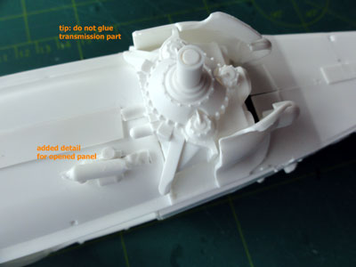
With a razorsaw the panel was removed.
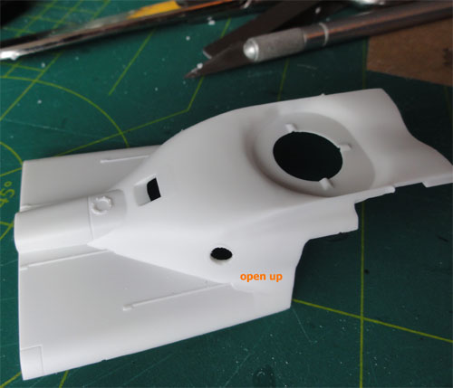
STEPS 38-39
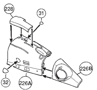
The Dutch Lynx has a slightly different
fairings layout as the kit parts here.
For the SH-14D:
- fairing kit parts #228+229 were
reduced in length at the rear section:
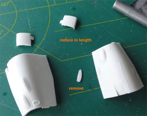
Also remove 2 fairing bulges that
are not seen of a SH-14D.
As noted, at the left side, a maintenance
panel will be kept open.
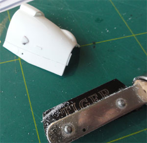
The panel opens up in two sections,
and some details and stringers were added inside from rod and sprue.
Fit the kit scoop parts #32 as indicated. In the side fairings #226A + 227A some tiny holes were drilled.
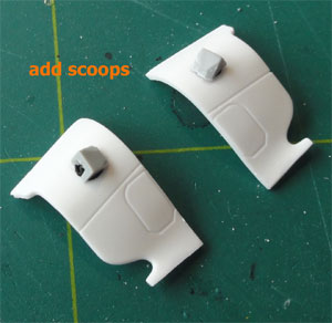
- on the intake guide panels #5, 6
each one got a large scoop made from card. They call the "cowhorn intakes".
STEPS 40-41
The kit exhausts are fine. There
is a seam visible but this is as in the real Lynx!
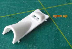
STEP 42
The upper engine fairings are assembled
with the intake plates. The scoop at part #211 was drilled open and a splitter
plate inside added:
STEPS 43-44
Do not open up the 2 holes at the
forward section in the bottom part #3A near the nose gear. For a SH-14D
some fairings are not seen whereas 2 other fairings should be fitted. Fill
any gaps.
 ...
...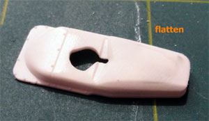
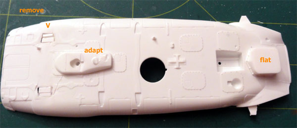
STEP 45
For the Dutch SH-14D, part #212 is
not needed but another smaller box/fairing is needed, so make from scrap.
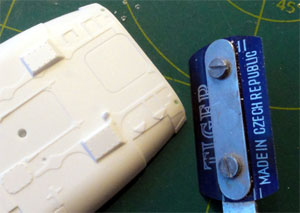
Part #231 should be sanded flat at
the rear area of this part (see above).
Also flatten part # 232 with sand
paper.
The various interior colours were airbrushed and handpainted with various coats of grey like FS36320 (Gunze #307) and light aircraft grey FS35237 (Gunze # 337) . To the wall covering panels, a handbrushed coat of Tamiya Smoke X19 was applied to give these depth.
STEPS 46-47
Some interior details were fited
made from card, strethed sprue and card.
 ..
..
The various sub-assemblies seen here.
The floor could be fitted inside
the fuselage halves. The small locating pegs at the floor rear sides end
were cutt of, this will enable fitting the floor. At the cockpit area,
the floor was not yet fixed and glued as the nose will need to fitted here
now...
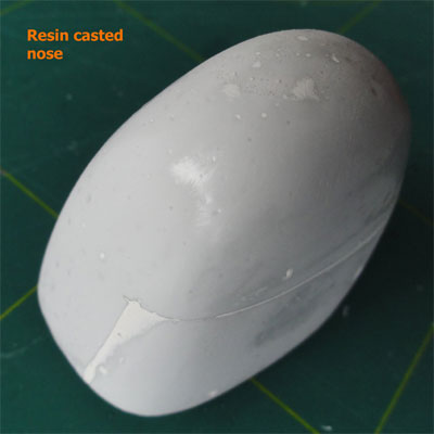
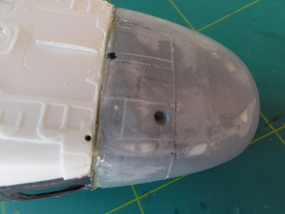
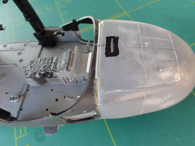
For the Dutch Lynxes such as the SH-14D the new resin nose is needed as casted, the kit nose parts are not required.
The resin nose panels were inscribed
with an OLFA P-cutter. Note that the panelling differs per Lynx version,
so check photos.
A round fairing from the spares box
was fitted in front of the nose wheel fairing as well as a ridge on the
altitude radar panel.
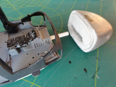
Now fit the resin nose with two component expoxy glue. Carefully align.
Also some gap filling is needed, use
rod and filler for this, Let dry and sand in shape to get a smooth join.
Note that the new resin nose parts are two, the bigger and smaller insert
part. To carry the resin nose weight, a piece of sprue was used.
 ..
..
It will take carefull adjustment
and filling the gaps with rod and putty and with some filler the result
is seen here:
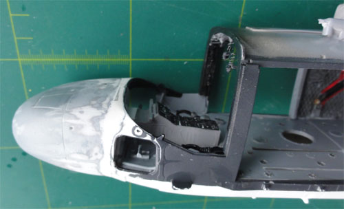
Note the typical Lynx kink in the
nose in front of the lower window.
An important assembly point has now been reached with a lot of work now done on this Dutch SH-14D Lynx model.
On to next [ Page 3.... ]
Back to 1/32 scale Models.......
(c) Copyright Meindert "designer"/ All rights reserved. Your comments are welcomed by webmaster
Created this page November 12, 2012