Hasegawa


Shin Meiwa US-1A model in 1/72 scale
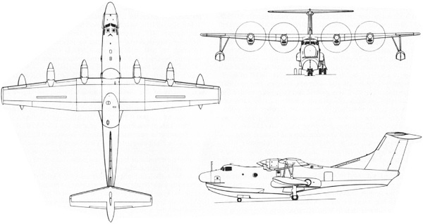
The Japanese consortium Shin Meiwa started design work of a new flying boat with a modified Grumman Albatross to do water tests. The new design was a large aircraft and the Japan Maritime Self-Defense Force (JMSDF) awarded Shin Meiwa a contract in 1966 to further develop it. An Grumman Albatross was heavely modified to test the concept as UF-XS. The type PX-S eventually got a unique wing with a blown flap design and for that purpose it has a 250 hp T58 auxiliary engine fitted inside the fuselage. It is able to fly quite slow. First flight was October 1967 of the PX-S. An anti-submarine version evolved into the PS-1 that carried its own beaching gear on board. The Japan Maritime Self-Defense Force (JMSDF) from 1966 placed the first order for 21 ASW PS-1 aircraft.
A few years later, a Search and Resue (SAR) version was developed. Designated US-1, it was an amphibian version with changed main Sumitomo built landing gear and fairings. Range was increased and they got side bubble windows and carry rescue equipment. The SAR versions are also ambulance/ 20 passenger capable and have a larger rear entry door. Some 6 US-1 and 14 US-1A (with more powerful engines) were put in service. (Shin Meiwa was later renamed ShinMaywa).
Some 14 aircraft are to be modernized to US-2 standard with new engines and systems, and the first modernized US-2 has entered service with the JMSDF in 2007.
Some data: wingspan 33,15 m. length 33,46 m; MTOW 43,000 kg. Max speed 520 km/hr. Range 3800 km. Crew of 12.
 ..
..
Hasegawa from Japan released a 1/72 kit for the Shin Meiwa PS-1 in 1971. The kit was released a number of times and I had newer in 2014 released kit US-1 #02094 "rescue ivory" as the SAR version.
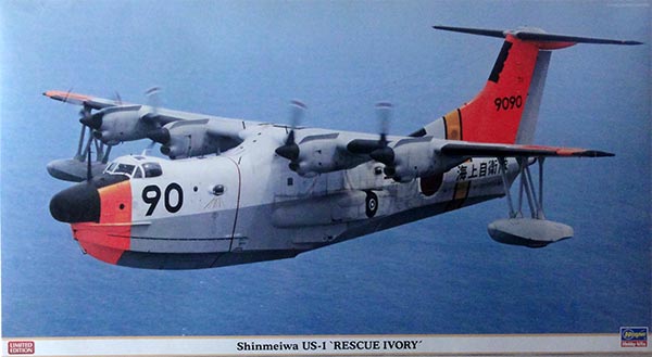
The old kit has two types of gear: still for the PS-1 and for the US-1 with bulbous gear fairings.
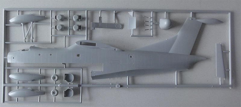
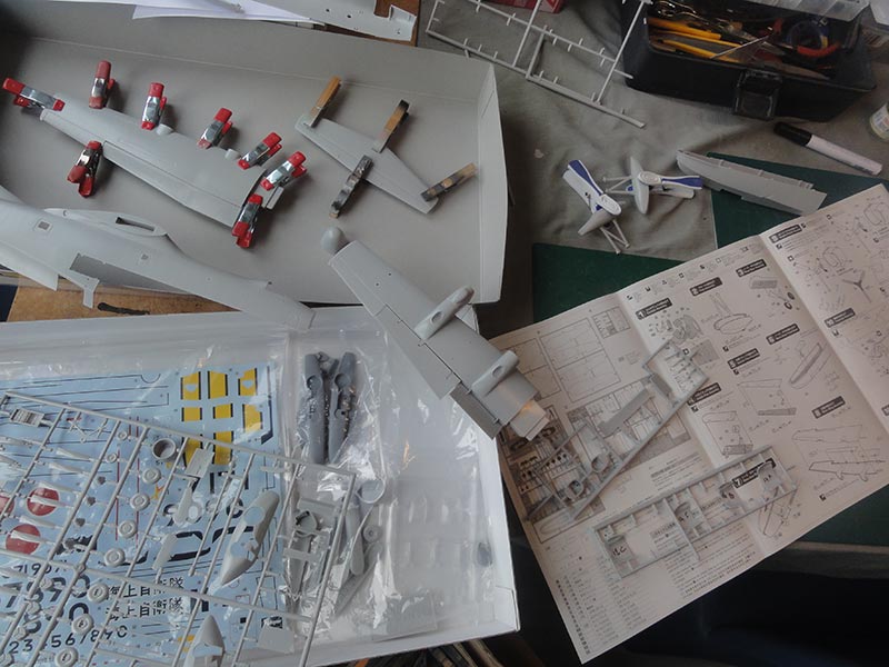
There are first some 150 parts in the kit (including many unused parts of the old PS-1 ASW kit).
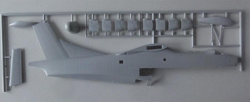
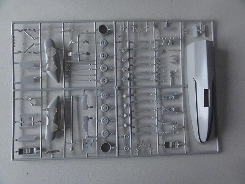
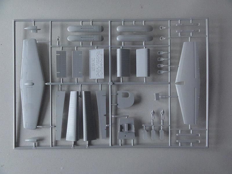
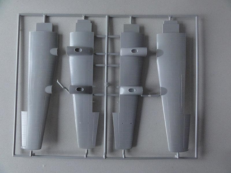
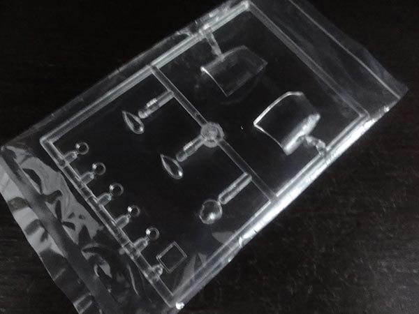
The newer released US-1 kit #02094 has 2 big resin PUR parts to replace the bulbous fairings. The new slimmer fairings are probably in the kit to make these more accurate for the US-1 amphibian.
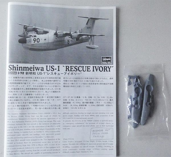
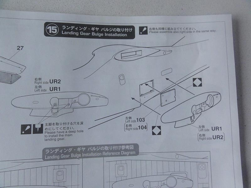
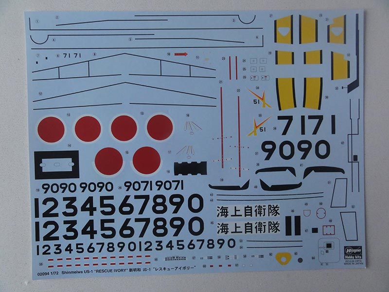
Decals are for [1] US-1A of 71 squadron and [2] US-1 based at Iwakuni. Several aircraft codes are on the sheet to be composed.
The Hasegawa kit shows its age but has very fine raised rivets which are worthwhile to retain as much as possible. It has movable flaps and only inside detail in the cockpit.
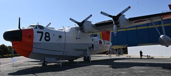
I had the pleasure to visit the Gifu Kakamigahara Air and Space museum at Nagoya, Japan. A US-1A is on display outside and I made a walk around and this is published on the IPMS.NL website (see references). My walk around was used to make this model a bit more accurate as US-1A coded 9078 / "78" with Shin Meiwa c/n 2008.
This modelling report shows a step-by-step approach.
STEP 1
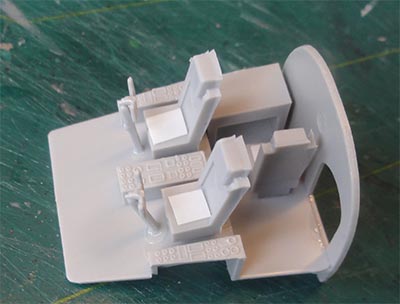
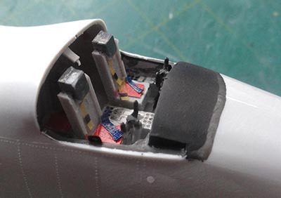
The kit cockpit interior is basic and can be seen through the various windows. Decals are provided for the instrument panels. I painted the interior medium gray, seat cushions and I added a few seat belts from slices of masking tape.
STEP 2 deals with the floats and STEPs 4 and 5 with the rear flaps and were done as shown.
STEP 3
Do not yet install the nose gear to avoid damage, just the gear bay #98 inside the hull.
STEP 6
The lower forward fuselage hull #50 does not really depict the water skirts; Hasegawa suggests to set decal stripes here. I opted to make the skirts on port and starboard a bit more pronounced with a scriber. The skirt gaps were suggested with a deep recessed line. At the end of the skirts I tried to represent the smaller flow plates and changed a bit the shape.
STEP 8 deals with main wing halves assembly. There are nicely interlocking lips to connect the wing halves to get less load on the joints.
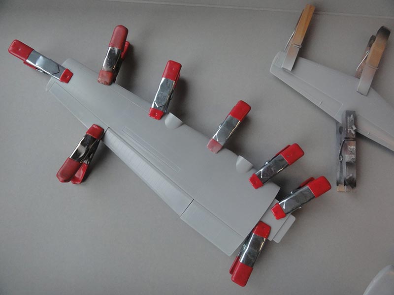
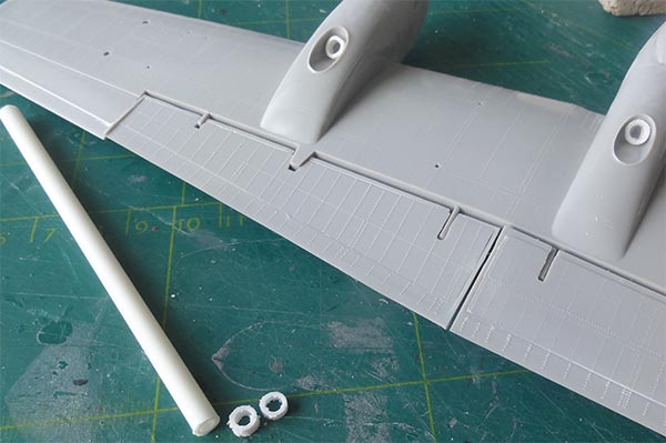
STEPs 9 and 10 deal with the nacelles and propellers. Leave the propellers for later. Mate the nacelles assembly with the wing fairings. Some sanding and putty is needed and after that set the small scoops #114. The exhausts in the nacelles are a bit simplified. I suggested these with small rings made from plastic tube set inside.
STEP 10 deals with the main fuselage.
Some windows are different on the US-1A as compared to the PS-1. Hasegawa shows to drill some holes in the fuselage halves. Some windows need to be closed up. I found that I missed a few glass parts, but may be I lost them...
The joints between the halves are weak so I set strips of plastic card inside. I suggested a bit cabin interior with paint but nothing will be seen later on.
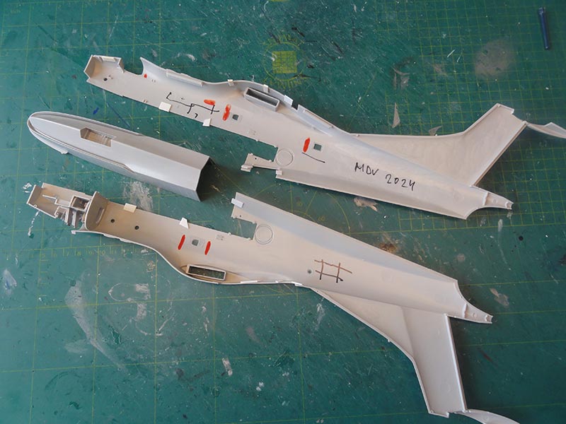
In this step it is also indicated that the US-1A has a big rear door; a decal is provided and fill the smaller engraved door lines.
STEP 11 will reveal that the top panel will not fit. Sanding is needed and again putty and sanding. Do strengthen the joints with strips inside.
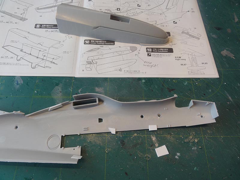
The lower hull should be mated with the upper fuselage, the joints are a bit weak so strips of plastic were again set inside to get stronger joints. Also try to glue a smooth joint to avoid sanding off the raised rivets.
STEP 14 deals with the stabilizer halves. Glue but do not yet install on the tail.
STEP 12 shows to assemble the fuselage and set the inside lower panels. Do not yet install the nose part #5, this is better done much later also to set the 20 grams nose weight.
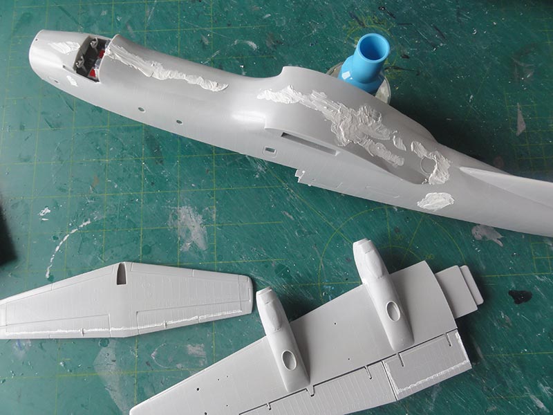
Sand and putty all joints.
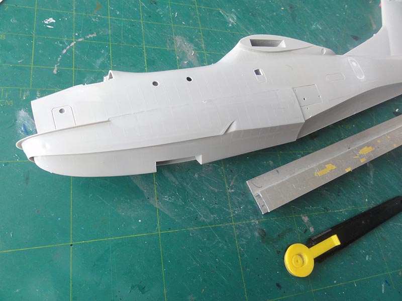
At the hull area and sanded spine areas I tried to suggest the rivets again with a riveter tool.
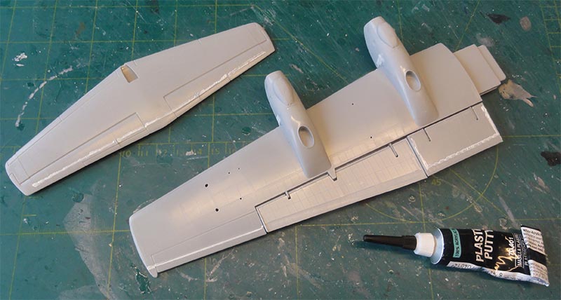
The small gaps in the flaps and stabilizer were filled with Vallejo Plastic Putty.
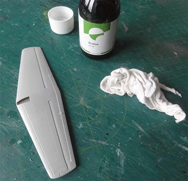
To avoid sanding off the rivets, allow 10 minute drying and than swipe off any putty with an acetone moisted cloth to get smooth results.
At the flaps, I saw a few raised plates. These were made from thin plastic card.
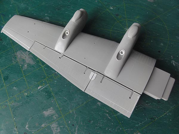
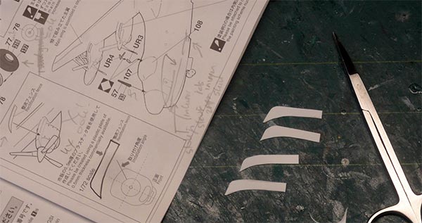
STEP 16 shows that US-1 and US-1A have flow guidance fences on the nacelle sides. Hasegawa shows these in the instructions with a template as the modeller needs to make these from thin card. Install on the nacelles. Any small gaps can be filled with white glue and smoothened.
Do not yet install any landing gears nor antennas on the fuselage.
STEP 17 shows the general wing-fuselage assembly, do not do yet.
NOTE: I forgot to install the small resin part #UR5 for the exhaust at the port tail base. This is better done now, see STEP 17.
Now, on the fuselage some extra details were added. The walk around was very helpful here.
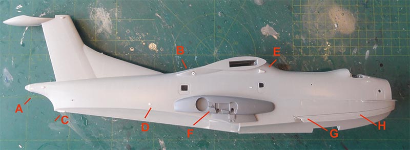
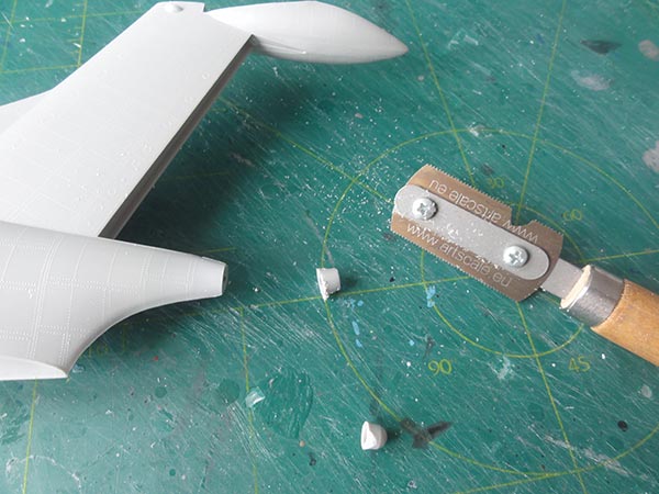
[A] I found that the rear fuselage cone is shorter on the US-1A as per kit. With a razor saw some 5 millimeter was cut off and puttied and sanded in a bullet shape.
[B] the inside turbine engine exhaust at starboard was drilled opened up and a small deep pipe installed. (The closed one at port was retained as per kit).
[C] at the rear fuselage boat shape, a small bumper was set.
[D] at the rear fuselage a small scoop was added.
[E] at starboard, a scoop fairing was also set below the wing root.
[F] as shown in STEP 15 the new resin PUR fairings were now installed. Their main gear holes were drilled open a bit wider with a drill first. Draw a pencil line as guide and check symmetry. Thick super glue was used to fix the fairing PUR resin parts on the fuselage sides.
[G] note here the small adjusted skirt ends.
[H] [K] the deeper inscribed skirt panels are seen here.
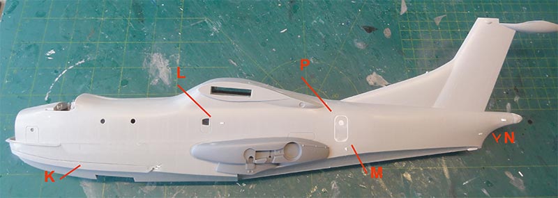
[L] a small raised plate was set here
[M] a small raised plate below the door
[P] the small rear door filled, a decal is provided for the larger US-1A door.
[N] add a few small smaller plates at starboard.
The cockpit glazing halves was now set. They will fit but putty and sanding is needed. Protect with masking tape and avoid spillage.
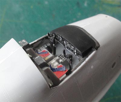

Note the upper roof windows that were also masked.
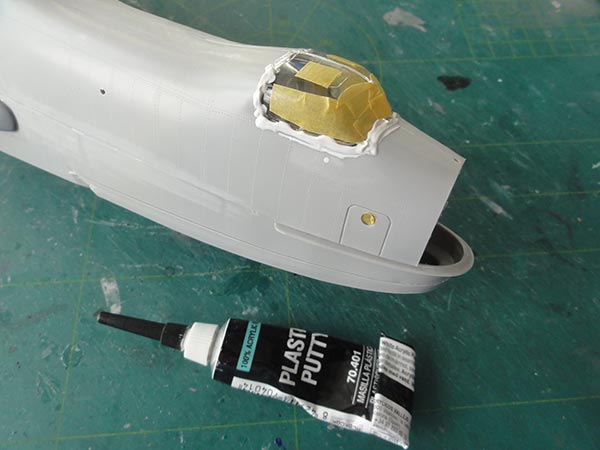
Carefully sand.
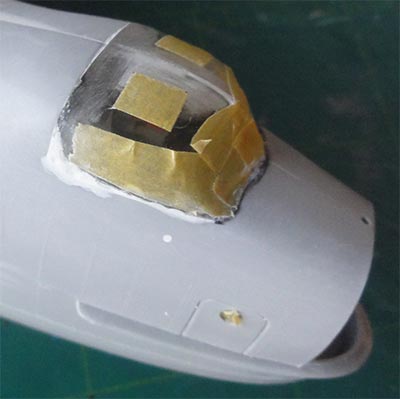
A dry fit showed that it is not needed to install the wing halves and stabilizers yet....
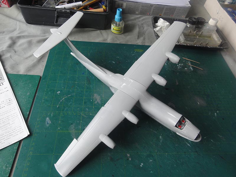
All looked smooth, the main assemblies are ready for first paint coats.
Mask off all windows.
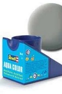
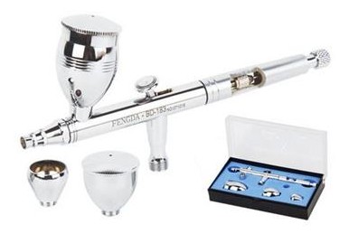
To check for any flaws and a gaps, as usual a base coat of grey was airbrushed. I usually airbrush thinned coats of Revell Aqua 75 stein grau acrylic for that. But any light grey primer paint will do the job.
When all looked good, time for next paint coats.
As noted, the US-1A coded "9078" will be made. The general colour scheme [1] is shown very well in the Hasegawa instructions.
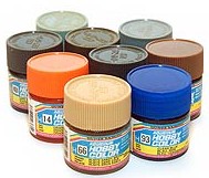
This colour scheme shows that wing halves, stabilizer and lower fuselage/ boat hull and outside floats are gull grey FS16440. These were airbrushed with Gunze Sangyo Mr.Color H315 acrylic. Do not forget the floats.
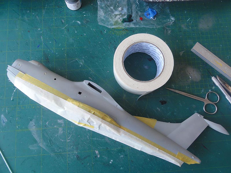
The upper fuselage is white, so masked off were now the gull grey fuselage and tail areas. Any gloss white will do but Gunze Sangyo H1 is a very fine acrylic paint to airbrush.
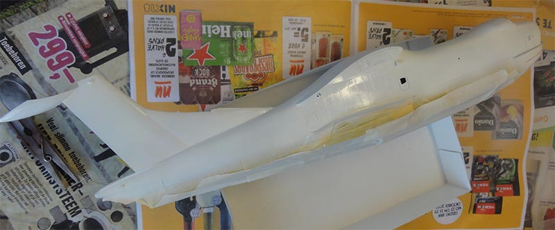
Some areas on the scheme are gloss orange. Hasegawa suggests Gunze H59. I did not have this paint so airbrushed Revell Aqua 30 orange acrylic in stead. Mask all areas obviously. I also airbrushed a spare bit of clear decal in case any repairs are needed later on.
The leading edges of wing and stabilizer are mat black as is a small portion at the tail base. Also some areas aft of the nacelles. Mask and airbrush at this stage.
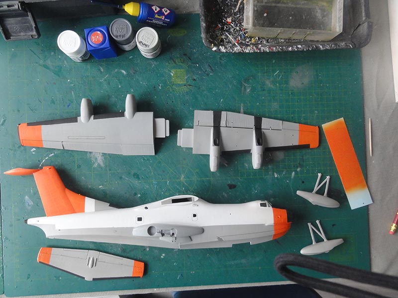
The main parts are seen here. It was checked earlier that the wing halves will fit very well.
Before decalling, the surfaces were airbrushed glossy with my favourite Johnson Future/ Pledge varnish. This varnish will airbrush very well when tinned 5% with acrylic Gunze Sangyo levelling thinner.
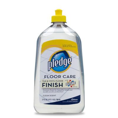
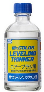
But any gloss varnish will do.

The surfaces are now glossy so the decals can now be set on the model. The kit decals need a lot of time soaking these in water and are a bit thick. The long wing walk lines and smaller stencilling are provided.
I found that the thick kit decals have a bit trouble settling down over the fine raised rivets. Use decal softener here.
The bubble windows on the fuselage sides were also installed, fix with very tiny blobs of white glue. I found out that I had forgotten the extra rear bubble port window seen on this US-1A. It was drilled open in the fuselage and I was lucky to find a clear bubble window in my spares box.
The result is seen here....
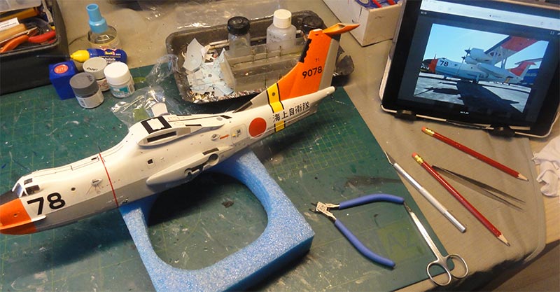
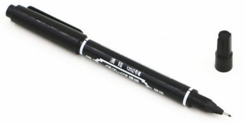
The red Japanese markings are a tiny bit translucent but I used them. Some very tiny stencilling is suggested with a fine pointed black waterproof permanent marker.
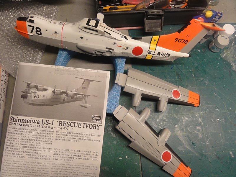
With decalling now all done, the main wing halves can be set. Note the interlocking wing lips. Carefully glue and ensure a good joint and I also used thick super glue.
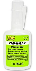

Very tiny wing-fuselage joint gaps still showed but these can be perfectly hidden with white glue smoothened out with cotton swabs. No need to paint.
STEP 13
The outside floats were set. But first black stripes on the struts were drawn with the black permanent marker. Small gaps at the outrigger joints remained. White glue filled these up and when dried hand brush painted gull grey.
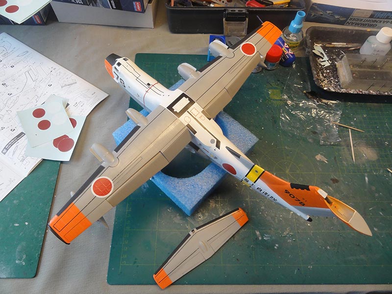
STEP 14 shows stabilizer installment.
I found there were gaps at the stabilizer - vertical tail joints. These were again filled with white glue and brush painted when dried. Also the top gap was filled.
STEP 16
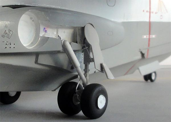
The landing gears were now installed as shown in this instructions step. The bay interiors were painted gloss white.
I found that I had to cut off some 3 millimeter on the inside pin of the main gear parts #105 and 106 as the main gears should sit closely to the fuselage fairings.
As the round doors sections #80 should meet each fairing gap, the outside pins needed removal as well on the struts. Parts #80 need to be split in two.
Ensure all the wheels touch the ground.
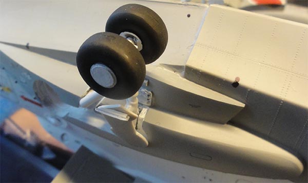
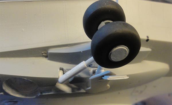
The nose gear bay was painted white inside and the strut #102 had not yet been installed earlier in STEP 3. To fit now, the strut locating pins had to be removed to squeeze them inside the nose gear bay. The gear doors were installed and inside a few hinge braces made from white stretched sprue.
Balancing the model is now done to avoid a tail sitter. I was glad that nose part #5 was not set earlier as no less than 20 grams nose weight was put inside. The nose part is mat black and fits OK.
The final small bits were now installed....
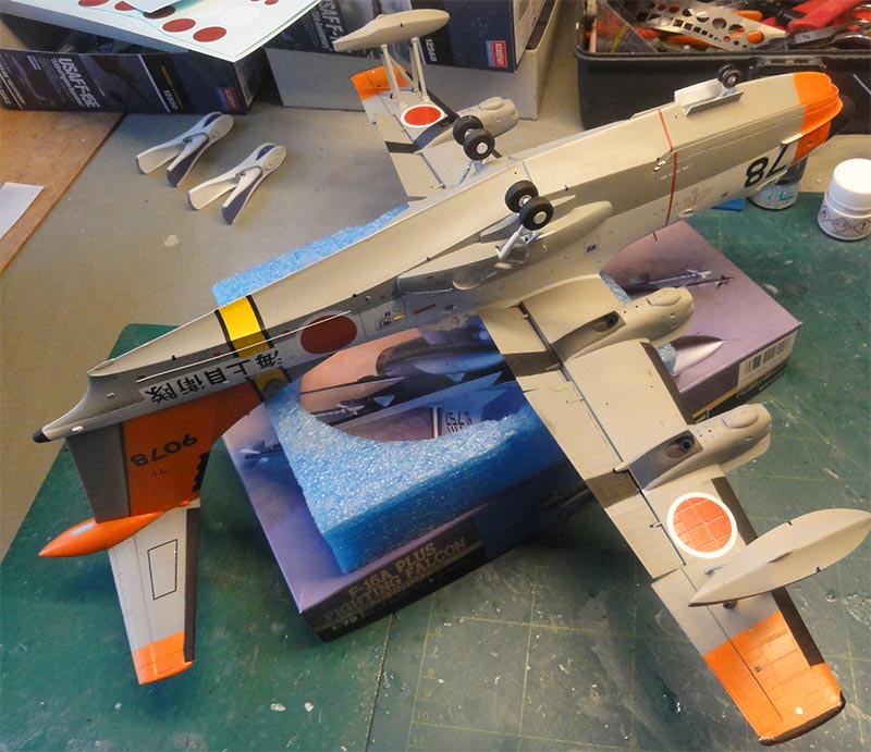
On the starboard rear fuselage a long rescue grab line is seen, this was suggested with stretched sprue. This line helps recovery of anyone in the sea that can than move towards the entry door.
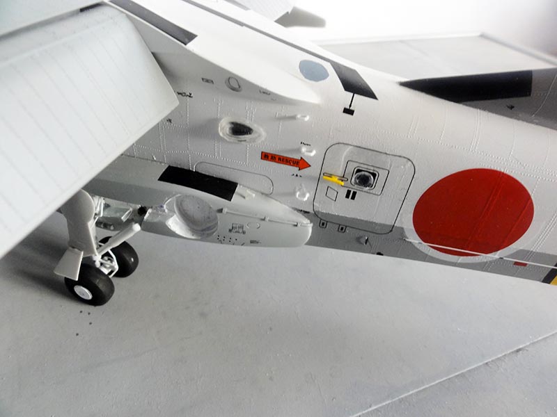
A small bit was set on top of the fairing as lock to attach any rubber boat line.
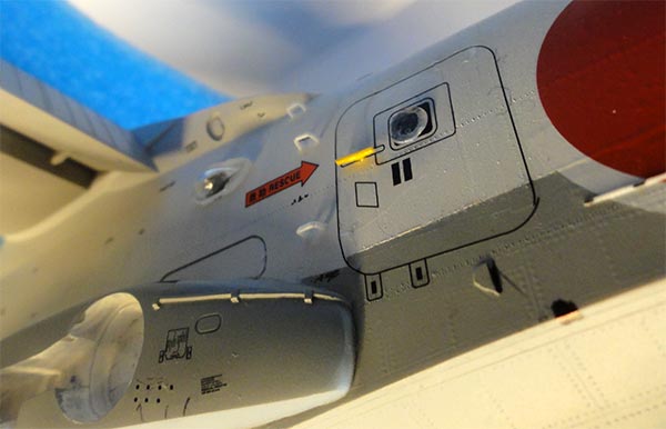
On the large door, a yellow rear door handle was set from yellow stretched sprue. A few climbing ladder sports added from white thin rod forward of the door. A crew member can climb to the spine as look out to search.
On the main gear struts a few hydraulic lines/ tubing were set made from thin white stretched sprue, set with super glue.
STEP 9 also shows how the propellers are assembled. I needed to drill wider each of 3 holes/ recesses in the spinners and bases. Set each blade at 120 degrees.
I painted the blade tip edges white, trimmed the tip stripe decal clear edges *(55) and set these.
Fix the propellers on the nacelles with white glue.
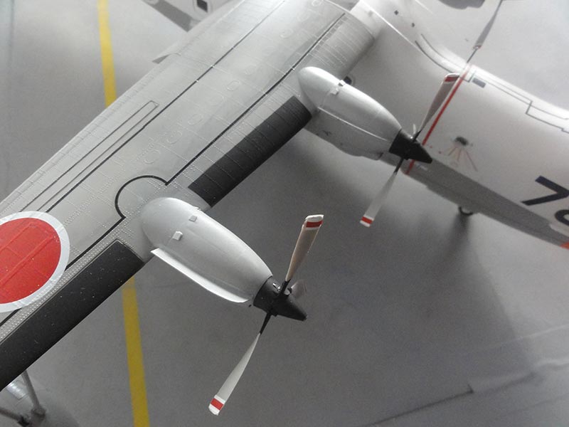
The movable flaps were also fixed in place. Here the special nacelle fences are seen clearly.
On this aircraft quite a few antennas and very long wire antennas were seen.
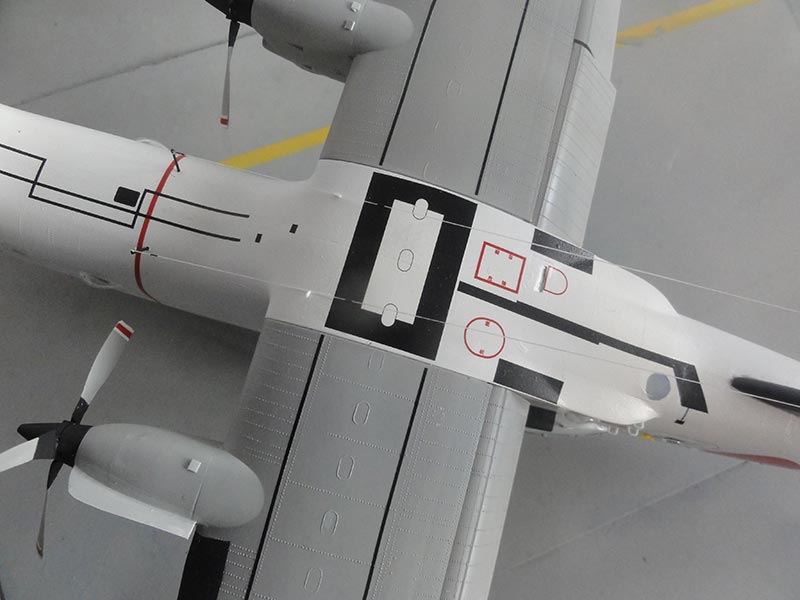
Two long HF antenna wires run to the tail and were made from PRYM elastic wire and set with super glue. (Fishing line will also do). Two tiny holes were drilled in front of the wing-fuselage fairing to set antenna masts made from rod.
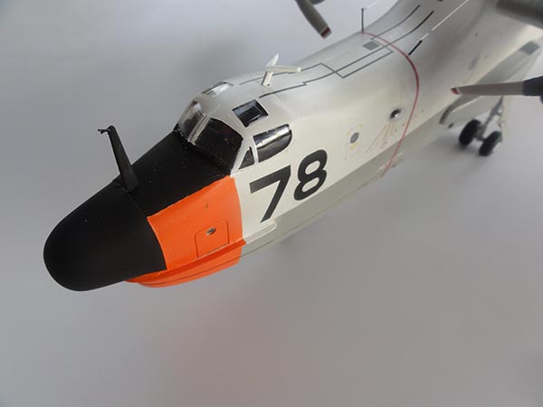
On the nose, mast #57 was set and I added very tiny pitot tubes from scrap on the top.
The VOR navigation antenna behind the cockpit is from a few resin parts #UR3+4 and was set. I also set 2 wind screen wipers from thin black stretched sprue. (hardly seen here).
Various static discharger wires are fitted on the trailing edges of wing tips, stabilizer and tail. Made from EZ Line bits set with super glue.
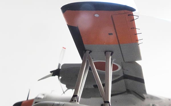
The floats are also well seen here with black stripes on the struts. Note also the tip lights. A tiny clear red light was added on the vertical tail leading edge "knob".
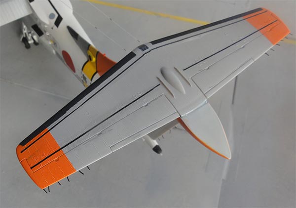
These aircraft are kept in splendid condition by their crews. Any salt water is sprayed off after each mission. So, the model was not weathered. I only added a bit wash in the insides' of flap and elevator gaps.
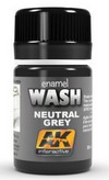
Finally a few gloss varnish coats were airbrushed to get a smooth finish and protect the decals. Again, Johnson Future/ Pledge was used but any gloss varnish will do.
That completed this very nice Hasegawa Shin Meiwa/ ShinMaywa US-1A in 1/72. Although the kit shows its age, with some effort a nice model can be made. Overall time spend was 38 hours.
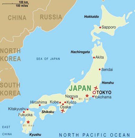

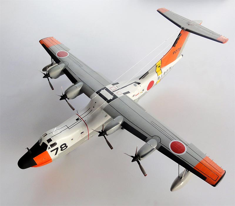
Shin Meiwa (ShinMaywa) US-1A, 71 squadron, JMSDF, coded 9078.
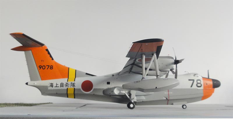
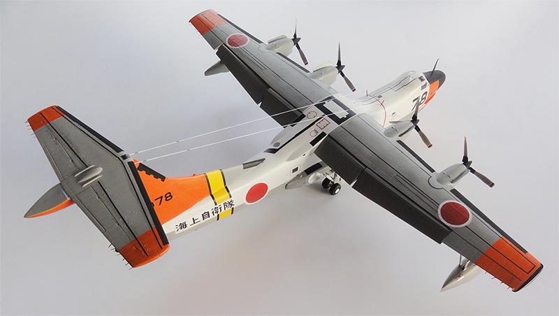
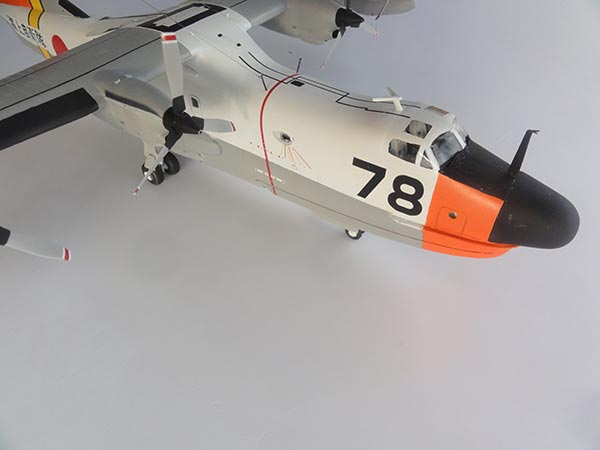
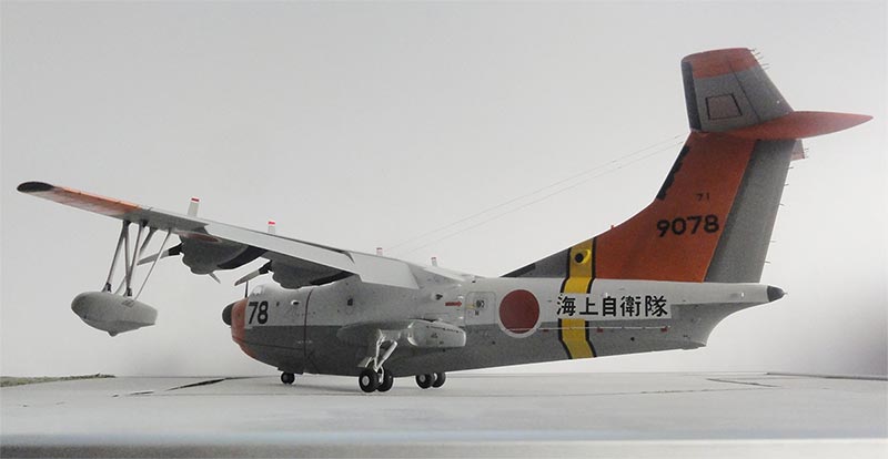
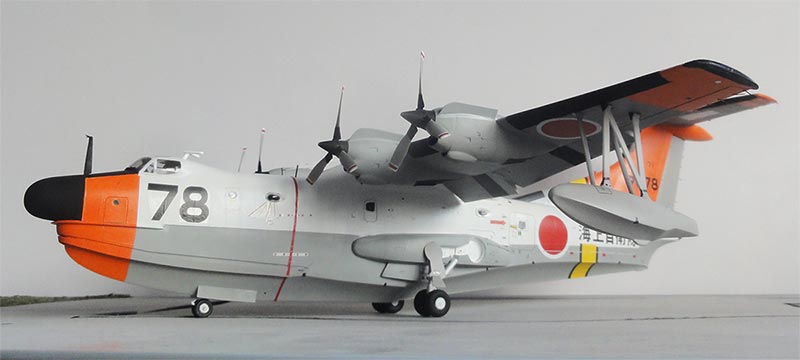
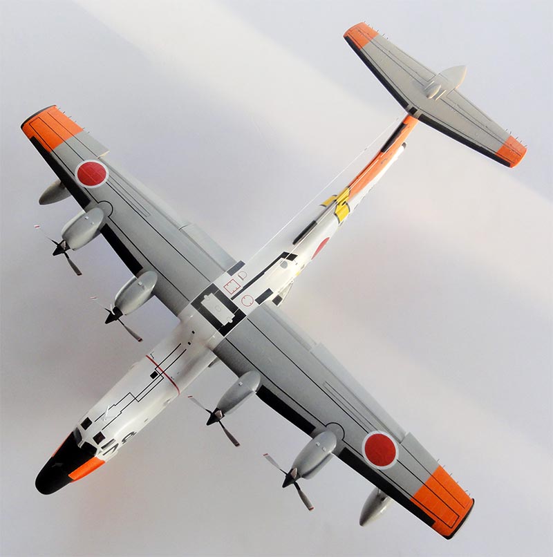
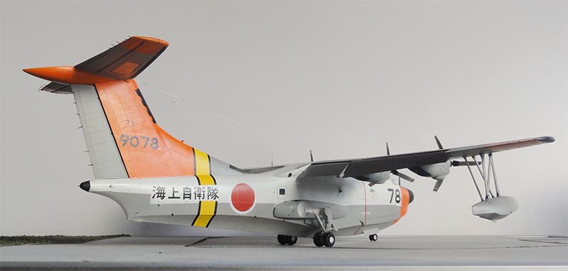
... set in scenery at Naha...
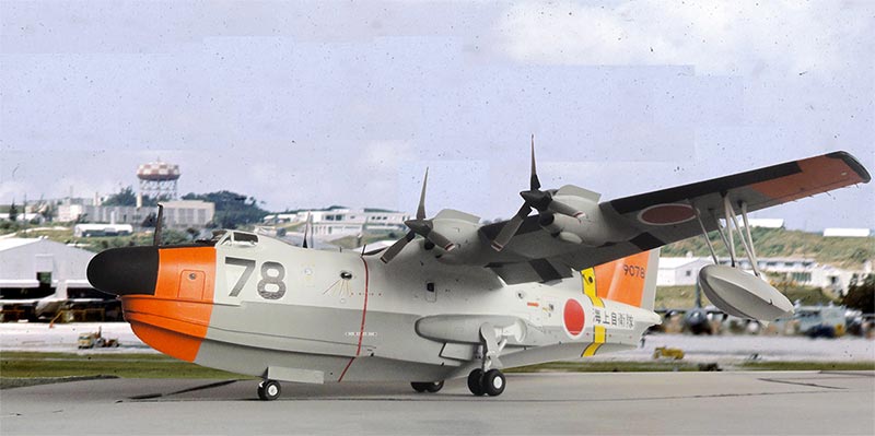
A nice model in the post-war Japanese aircraft collection.
* books:
- World Air Power Journal, David Donald, Vol. 15, pages 126...
- Air international magazine Vol.22, pages 78...
- Air international magazine Vol.69, pages 528...
- various photos in BUNRIN DO / Koku Fan
* internet:
- Meinderts own Walk Around on IPMS.NL
- Wikipedia

(c) Copyright Meindert "designer"/ All rights reserved. Your comments are welcomed by webmaster
Created this page
November 15, 2024