"B one"
[ page 2 ]

Revell Rockwell B-1B model in 1/72 scale
page 1
... continued from page 1..
STEPS 1,2
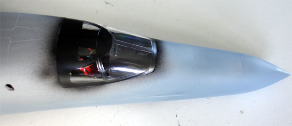
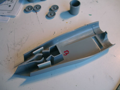
Start with the cockpit area.
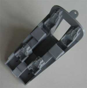
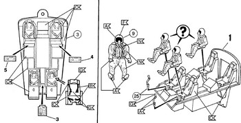
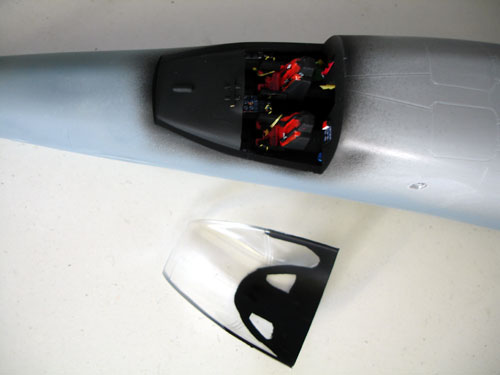
Adding some details is worthwhile here, for example substituting the seat with ACES II from Neomega. There is also a "Goffy cockpit detailset" but I never saw it.
Although not much can be seen through the windows inside the cockpit, I used the kit seats but bothered to add armrests, red cushions and harnesses from slices of tape. Some details were suggested with scrap plastic.
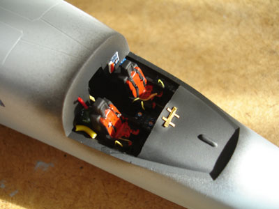
The instrument panel was painted light grey, the coaming black and some spare instruments decals applied. The majority of the interior was painted dark grey. In side of the canopy frame was painted black.
STEPS 3,4,7 & 9
The major assembly of the fuselage can be done now with inclusion of the assembled corrected wing halves. As noted, the wing root gloves were reduced in thickness previously to get a much better look as were the wings.
Inside the nose you need to add about 40 grams to balance the model.
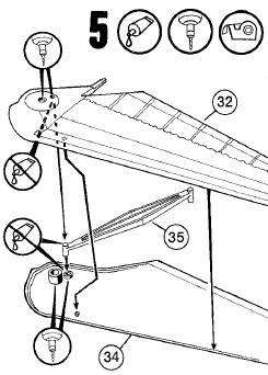
Taping is needed to hold the fuselage together, take your time here and align the long joints. The wing connect rod #35 was also used.
The seal area behind wing will be covered with a decal later on.
Some putty and sanding is needed. Some panellines were again rescribed at the puttied areas. The overall shape is much better now.

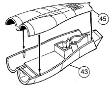
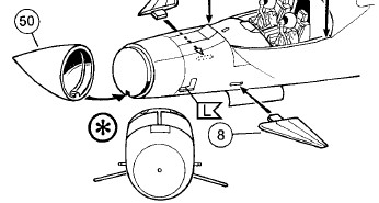
STEP 8
Not needed, already preparations were done on the fuselage.
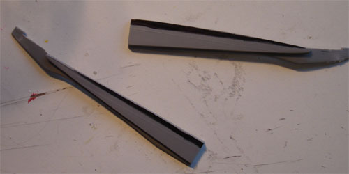
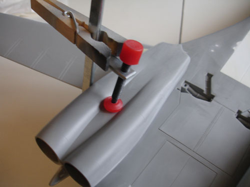
STEPS 10,11
Assemble the stabilizers as shown. I removed the locking strips on the aixles. Do not fix the stabilizers yet.
STEP 12
At the base of the rudder, I removed the moulded stub on the fuselage. The vertical tail itself should get an ECM fairing on top. With some plastic card and putty this was made.
STEP 13
The end cone of the fuselage is 4 mm TOO SHORT and should be a bit pointier. I inserted round sections of card glued together at the front of the cone part #51.
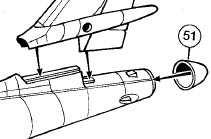
Fix in place, let dry overnight. Than sand in shape and use filler / putty as needed. Note that you need to reduce thickness on the cone but take care not to remove too much plastic here. The overall look is now much better.
The "Towed Decoy" fairings be also be made with card, but this was a later modification of the B-1B so it is not really necessary. I did not make them.
STEP 14
Do not fit stabilizers, leave for later.
STEP 15
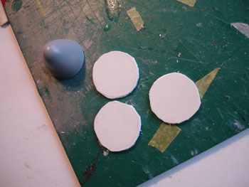
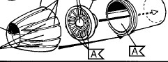
Next are the engine pods. The strange tri-angular shapes on the bottom of parts #44 + 45 should be sanded off.
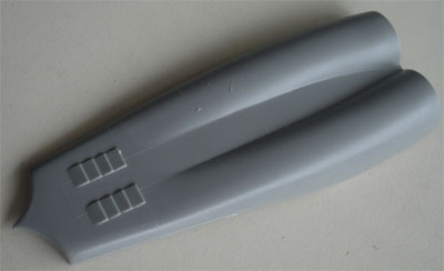
Inside the intakes, air intake flow guidance plates are present on the real B-1. These were made from card.
The pod fit needs sanding and fillling.
On the back of each pod just before the exhaust, some small aerodynamic fins are seen on the real Bone. Make from thin plastic strip.
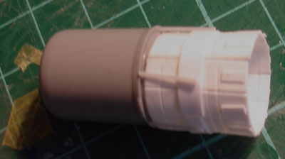
STEP 16
The engine exhausts have the "turkey feathers" covers, but they were never applied to operational aircraft. Think of a similar situation as in the F-15 Eagle, where these feathers but were usually omitted to save weight and ease maintenance. That means that the exhausts therefore look very different.
Cutting Edge resin set 72030 can be used for the exhausts (this set will cost nearly as much as the kit itself!). Alternative: cover the exhausts with ground protection covers.
I decided to make the four F-101 engine exhausts with numerous details from plastic card, strip and rod. Quite some work, but the result was OK for me.
STEP 17
Do not fit the exhausts yet to the model, leave for later.
STEP 18
Fit the engine pods to the lower fuselage, some putty is needed here.
Skip the undercarriage assembly for a while, move to...
STEP 41
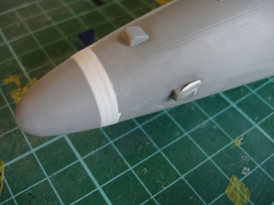
Fit the radar nose. The nose angle up is a bit too much. Some filler was applied at the lower area of the nose cone and the top was sanded a bit. The overall shape was now better.
The vanes (parts #8) were reduced in thickness and are to be fitted later on. They should be set at quite an angle downwards.
STEPS 36-40 not needed
STEPS 44-47
You can add a crew entrance ladder. I set everything closed.
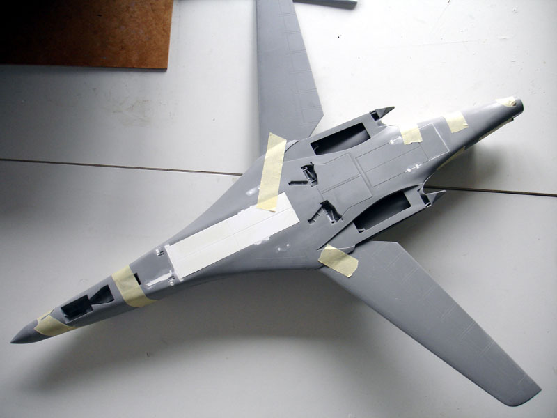
Now it was time to add some tiny antennas to the model before airbrushing. On top of the fuselage, 2 large antennas made from card were added. Many airflow vortex generators were added below the horizontal stabilizer area (2 x 11 parts made from thin strip). I did not add yet the many small pitot tubes at the nose, this was done later.
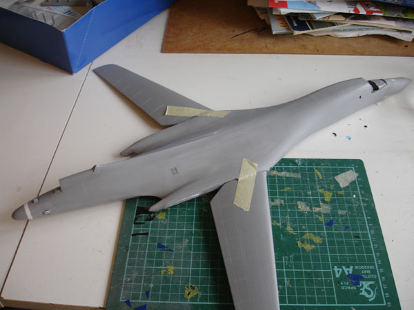
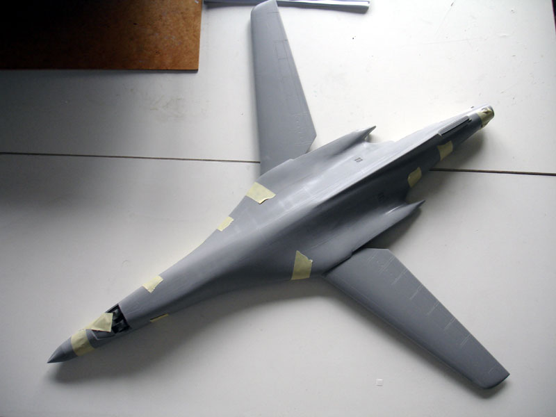
The basic airframe of the model was now assembled.
Before fitting any undercarriages and other details, I decided to airbrush the model first as it is easier to handle. The stabilizers were left apart.
Go to next [ Page 3..]
Back to 1/72 models...

(c) Copyright Meindert "designer"/ All rights reserved. Your comments are welcomed by webmaster
Created this page June 25, 2008