[ Page 1 ]
1/32 scale Hunter T-7 FISHER conversion of Revell kit
.... to main Hunter page....
Page 1
Page 2
Page 3
kit review modelling report
FISHER MODEL AND PATTERN issued
a conversion set for use with the injection moulded 1/32 Revell kit.
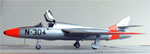
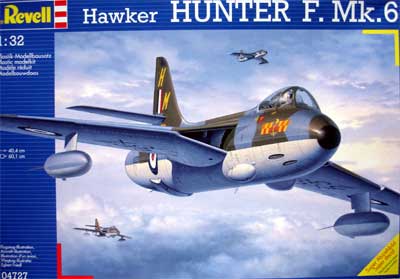
In 2006 Revell issued a Hunter F.mk6
kit (No.04727 ) and that can be used, but also the Swiss kit FGA9/mk 58
can be used if you only get your hands on this one. The conversion set
was ordered directly from the USA.
http://www.fishermodels.com
![]()
Decals are available from FLEVO
decals for a Dutch AF Hunter T.7 so what would prevent me making a
nice 1/32 model?
A great walk around of the T-8C is
seen on the Dutch
IPMS website here.... (Note: the T-8C Hunter looks a lot like
a T-7, but is seen with red anti-collision lights at the spine and in front
of airbrake and it has an arrestor hook. On the Dutch T-7 Hunters, these
are not present. Also in the T-7 cockpit, gun sights are present).
![]()
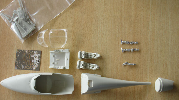
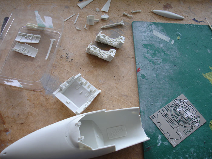
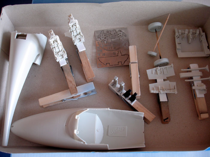
The main parts in the FISHER MODEL
AND PATTERN HUNTER T-7 Conversion set are resin main parts, metal undercarriage
legs to carry the heavy weight, etched metal instrument panels and details
and a clear resin canopy and windshield. Also RAF decals are provided.
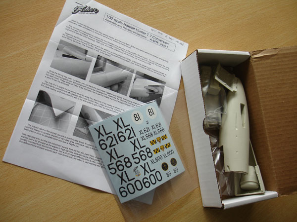
You get a written set of instructions
with the conversion set along with assembly photos.
Working on the resin parts,
separating them from the casting moulds:
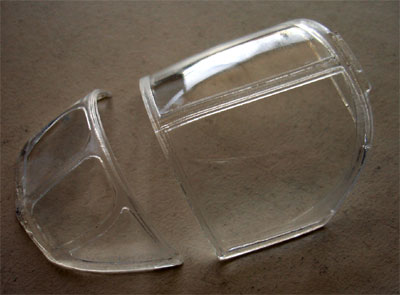
The resin moulded two seater canopy. It will benefit from dipping it into Johnson Future/Pledge acrylic coat to have a better shiny look. The canopy is very fragile so take care not to break it!
 .
.
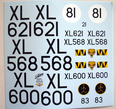
Decals for RAF planes in the FISHER
set:
 .
.
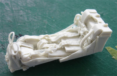
Two very nice Martin Baker seats are
provided with the FISHER set:
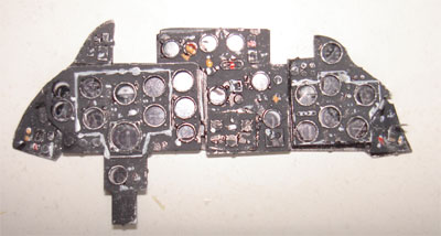
The instrument panels are also included
and have several etched metal plates as seen here:
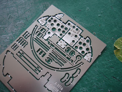
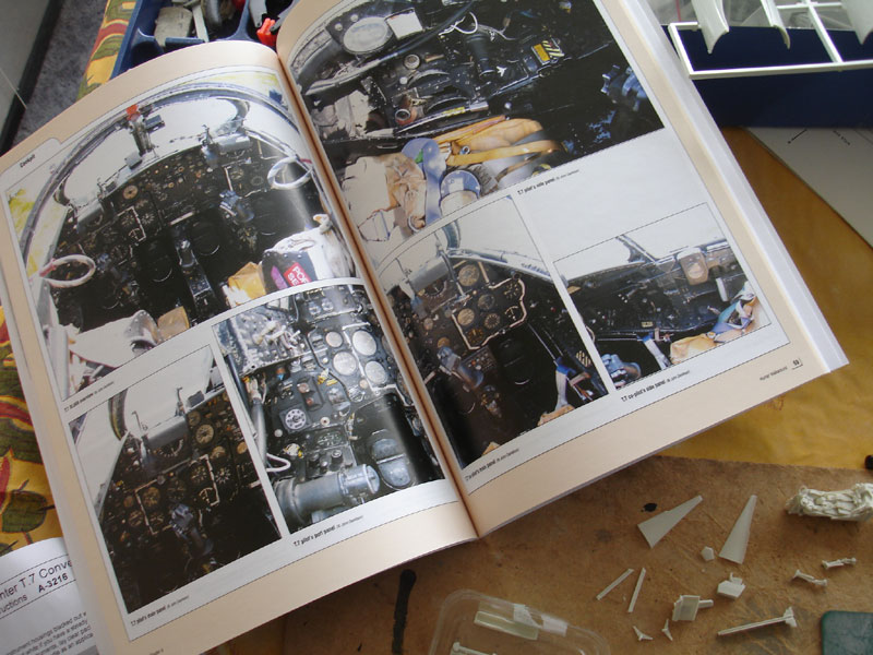
How the real T-7 panels look like:
The FISHER parts were separated from
their moulding blocks, cleaned up and ready to get a first coat of light
grey
On to assembly using the Revell F.mk6 instructions of the Revell 1/32 kit. (for the FGA9/mk 58 step numbers indicated are slightly different). Please note that the STEP numbers here are based on this F mk.6 kit's instructions.
Step "0" Model preparation
The Revell kit spine should be reduced
in length, do not use the incorrect figures of FISHER but measure
your self using the forward FISHER fuselage and spine as a guide.
Indeed do not fit at this stage the new resin spine to the resin cockpit, the cockpit floor will not fit through the remaining opening. So it is important to finish up the cockpit interior first so far that the floor can be fitted.
Steps 1-8
can be skipped as they deal with
the cockpit, use the FISHER instructions.
For the smaller resin and metal parts CA glue was used, for fixing the larger parts 2-component expoxy glue.
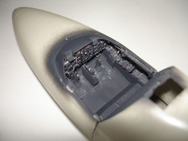
The FISHER floor is very very thin
and I think the depth a bit undeep, probably the nose gear bay is a bit
to deep. But nothing that is disturbing. For the cockpit numerous details
were prepared such as the side walls and assembled, ready for installment.
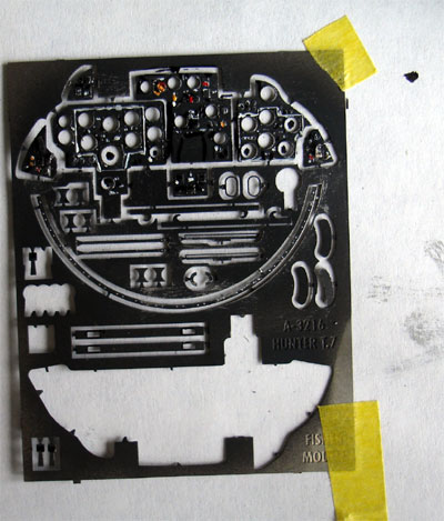
The frets and interior were airbrushed. Working on the T-7 cockpit interior,
using several layers with the FISHER parts and the supplied decals:
 .
.
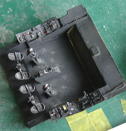
The overall colour of the Hunter
cockpit is "black" as common for fighter types of that period. A dark grey/black
mix
was used including drybrushing
to
show of the detail and to prevent a "coal hole". (obviously do not fit
the seats yet). 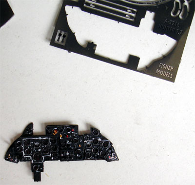
Dials and instrument are provided
as well in the FISHER set, to be set aft of the panel. The instruments
were covered by transparant Micro Kristal Clear later on.
 .
.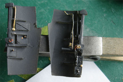
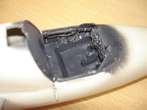
All the cockpit parts were fitted
in the resin nose, this is needed prior to fitting it to the rear fuselage.
The side walls need some trimming at there lower edges by about 3 mm otherwise
they do not fit.
The hole for taking the swivelling
canopy mechanism should be kept clear, a covering plate is provided in
the set.
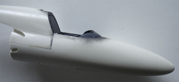
Some filling and sanding is needed
at the sides, but this can be easily done now at this stage and not later
as to avoid the intakes obstructing the work. The finished forward cockpit
and nose section was set aside.
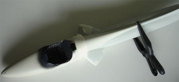
Now I continued with the rear fuselage.
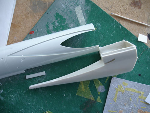
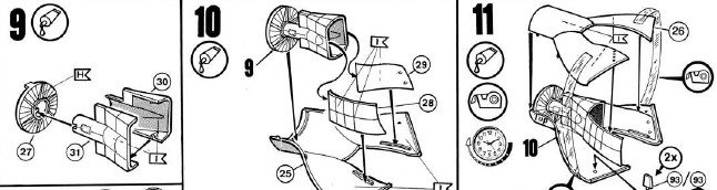
Step 9
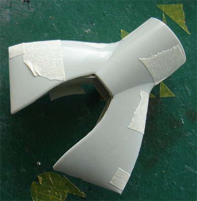
The main intake duct. Fill the ejector
pin marks in parts #25 + 26, paint and assemble as shown. The intake ducts
take tape to glue them correctly.
 .
.
Steps 12-13 can be skipped for now.
Step 14
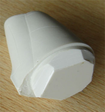
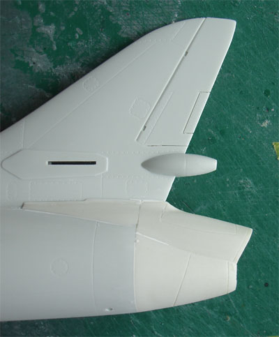
Use the FISHER rear end part. I cut
off the sides of the resin exhaust part for a better fit:
The rear fuselage requires some tape
and persuation to get a good result.
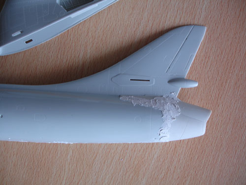
Some filling is needed to get a nice
result at the exhaust area with the parapack fairing. Take care with the
fragile thin fairing edges.
 .
.
Steps 19-20 can be skipped
Step 15
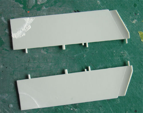
The trailing edge droop flap (parts
# 41 and 48) have a small cut-out for the larger wing tanks. On the mk.4
and T-7 these were not present. Simply cut of the corner of the lower wing
halve and reposition onto the flap. Fill and sand.
Step 17
Assemble the wing as shown in the
Revell instructions.
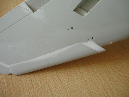
IMPROVEMENT
SUGGESTION:
The openings
for the inner pylons (see STEP 43 -46) for the 100 gallons tanks are too
far outboard and should be positioned 2 mm and in parallel with the leading
edge in 1/32 scale more inboard! This will improve the look of the Hunter
model.
Make new holes
and fill up the incorrect holes.
Also, the wing
sawtooth should extend 4 mm more inboard as compared to that on the kit.
I added this extension on both wing halves with card and putty.
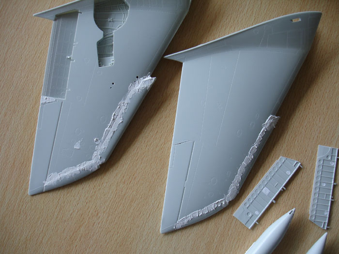
The wing root slots were opened up
and the leading edge extension filled and sanded. The aileron edges were
sawed to get a see through effect with the razor saw.
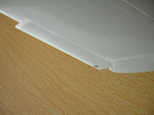
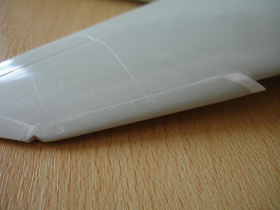
The completed and corrected LE extension
tooth.
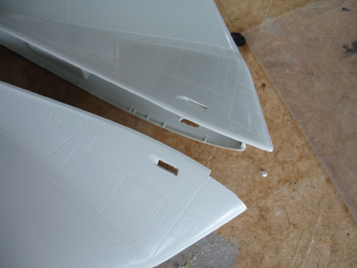
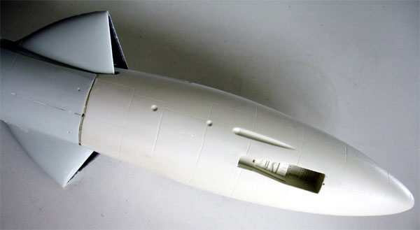
The intake slots were cut open as
well.
Step 18
Skip for now, leave for later.
Steps 19-20 can be skipped as the exhaust has already been fitted.
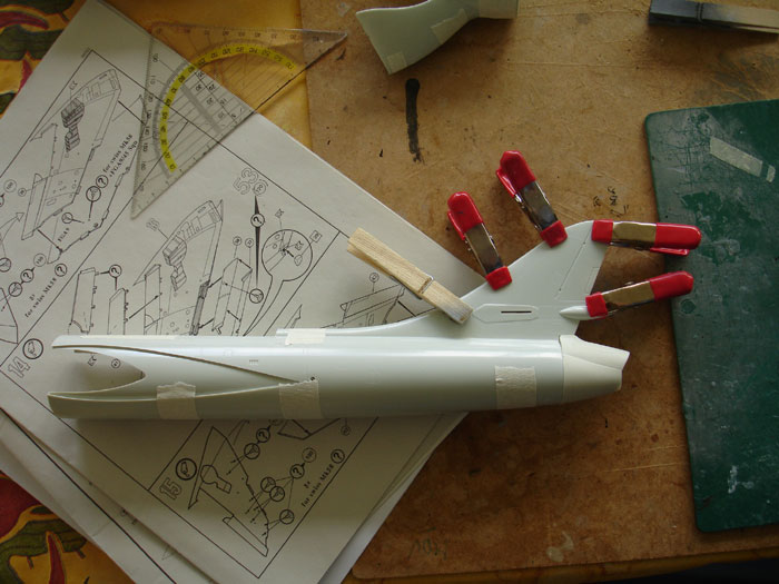
Step 13
The intake ducts are now set inside
the rear fuselage, but not yet glued in place. Next was fitting the T-7
forward fuselage to the rear fuselage.
Sand and putty the whole fuselage
with exhaust + main + front sections as needed now as you can now easily
handle the fuselage. The lower area needs filler and considerable
sanding... There is a "step".
.
Back to 1/32 Models.......

(c) Copyright Meindert "designer"/ All rights reserved. Your comments are welcomed by webmaster
Created this page
June 25, 2010