1/32 scale Revell
[ Page 1 ]
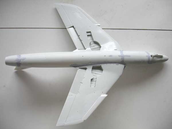
1/32 scale Hunter mk6. of Revell kit
The Revell kit of the F.mk 6 (no.04727) was issued in 2006 and was really welcome as it represent an important variant of the Hunter. It uses many common parts' sprues of the earlier issued Hunter kit of the FGA9/mk.58.
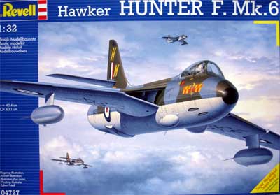
All the Revell Hunter kits are very good and well researched. The kit is very accurate, has good outlines and fits very well. But it can be improved in some small areas; this will be covered in this modelling report. Parts have finely engraved panellines and the intake and cockpit are captured very well.
Download kit instructions 04727.PDF
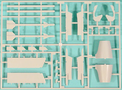
To cater for the F. mk6 version, you
get an extra sprue containing the F mk.6 differences
like exhaust without parachute fairing, slightly different split flaps,
early Sidewinder missiles and their outboard wing pylons. Also, you get
different ejection seat parts for the 2H used in most F .mk6 planes.
 the
extra sprue
the
extra sprue
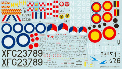
In addition, a new decalsheet is
provided with excellent printed decal. Decals are provided for the RAF
92, 56 squadrons and RNeth AF squadrons 324 and 325. Also decals for a
Belgium AF squadron 22 smaldeel Hunter is provided. (more on the Dutch
markings later on...)
This F6 model of the Hunter will
be made in a typical Royal Netherlands AF Hunter of the nineteen-sixties.
See for a brief Hunter history the
main
page here.....
![]()
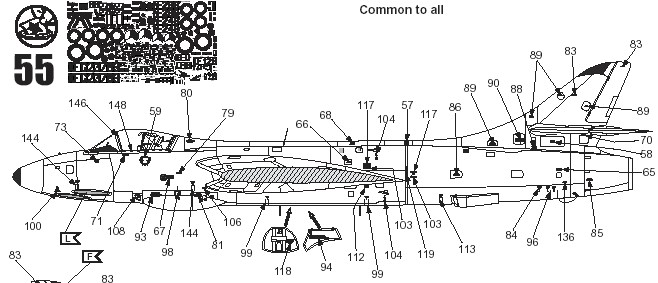
As "an always first", some parts got pre-painting while still in their sprues. Some assemblies were even made in the sprues. Examples are "tyre black" details of tyres , cockpit tub and bulkheads, ejection seat and instrumentcover part #20.
An aluminium coat was put onto the gear legs, some smaller parts and undercarriage bays.
Now on to assembly of the F6 or mk.6, which is relatively straight forward (as compared to the mk.4 which need conversion).
Please note
that the STEP numbers are based on this F mk.6 kit's instructions.
STEP 1+2
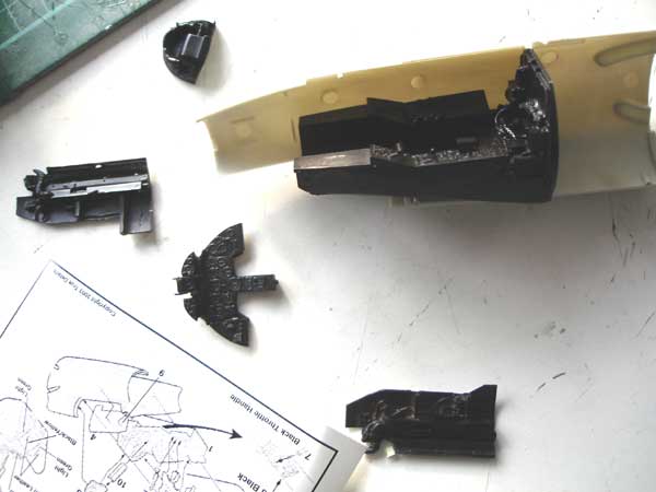
The ejection seat provided in the Hunter F.mk.6 kit is quite nice with two choices, for a 2H and a 3H. The RNeth AF used mostly the Martin Baker 2H seat; the 2H seat has "higher curved" plates on the sides.
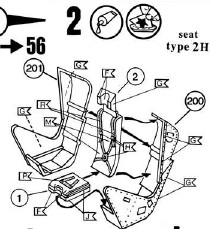
At first, mk.6 Hunters got the 3H seat but often were later on retro-fitted with the earlier 2H seat. There are also different types of grip handles on top of the head rest sometimes seen on MB seats, so check pictures.
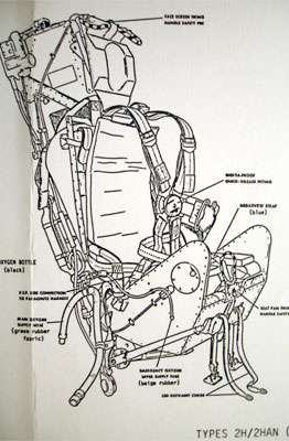 2H
2H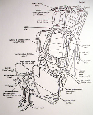
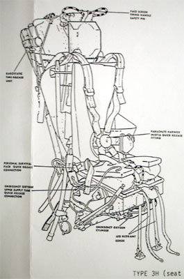 3H
3H 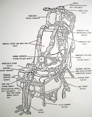
Here you see the Echelon kit seat drawings.
Alternatively you can buy aftermarket
resin seats.
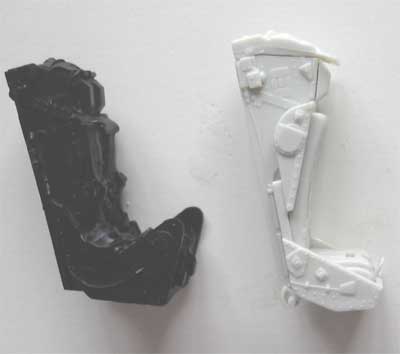
Martin Baker
2H seat of True Details on the left and Revell kit 3H seat on the right.
The True Details seat has another shape and is not so high as the Revell
one. When adding some details like seat straps and so on to the Revell
seat, I think it will be the better choice. (will be done later).
STEP 3
The main instrument panel of the
mk.6 is provided as part #13. You may drill out the instruments, create
the individual dials and plates. But overall is will be very dark.
Overall the kits' cockpit is well
detailed.
As I already had purchased a TRUE
DETAILS cockpit detail set (NO. 32453 ) for the ECHELON kit, I used
this resin set in stead of the Revell parts. It is noted however
that it is not really necessary to use a resin set as the Revell parts
are also good.
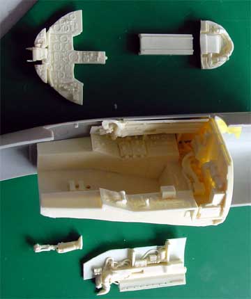
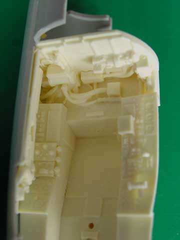
True Details set
STEPs 4+5
The overall colour of the Hunter
cockpit is "black" as common for fighter types of that period. A dark grey/black
mix was used including drybrushing to show of the detail and to prevent
a "coal hole". (obviously do not fit the seat yet). I did not fit part
#15 until later.
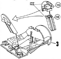
STEP 6
I filled up the hole in part #19
for the RNeth AF Hunter mk.6. Assemble as shown.
STEP 7
The nose gear unfortunately needs
to be fitted to be a strong assembly. Add a piece a card to close the gear
well.
NOTE: you may open up the gunports as you wish in part #21. Look at pictures of the particular Hunter you want to model. See also step 53.
STEP 8
Assemble, but leave instrument cover
#20 for later.
STEPs 9, 10 and 11
The internal intake is a very nice
feature. Fill the ejector pin marks in parts #25 + 26, paint and assemble
as shown.
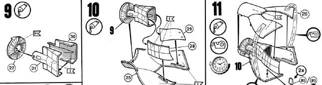
drawing : Revell
STEP 12
Assemble as shown, make sure to add
weight.
Skip STEP 13 for later on.
STEP 14
Rear fuselage can be assembled, make
a cut in the lower rudder edged to show it better.
STEPs 15 - 17
Assemble the
wing as shown. Cut off the indicated flap part moulded on the lower wing
trailing edge. You will notice that Revell provides you with a couple of
new flaps which is correct for earlier versions (mk.4, F.mk.6 etc).
![]()
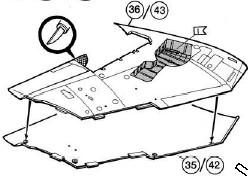
IMPROVEMENT
SUGGESTION:
The openings
for the inner pylons (see STEP 43 -46) for the 100 gallons tanks are too
far outboard and should be positioned 2 mm and in parallel with the leading
edge in 1/32 scale more inboard! This will improve the look of the Hunter
model.
Make new holes
and fill up the incorrect holes.
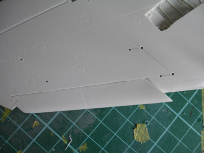
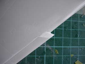
Also, the wing
sawtooth should extend 4 mm more inboard as compared to that on the kit.
I added this extension on both wing halves with card and putty.
![]()
STEP 18
This is a very important stage in
the model construction. Do this step in two parts!
First join the rear fuselage from
step 14 to the front section of step 8 .
DO NOT FIT WING HALVES YET!
STEPs 19,20
Assemble as shown. The correct large
diameter mk.6 exhaust is provided with this kit.
Next....
Sand and putty the whole fuselage
with exhaust + main + front sections as needed now as you can now easily
handle the fuselage.
The overall fuselage is now ready for further taking on the wing halves.
Refer to Revell instruction STEP 18
to assemble the wing to the fuselage. You will find that it may be necessary
to cut off some of the plastic thickness sligthly on the insides of the
parts on the forward bend edges of the wing intake gloves to get a snug
fit. I also had to remove 1 mm on the rear wing root junction.
The inner intake can be snugly glued
into the wing intake gloves.
STEP 21, 22
Assemble stabilizers as shown, but
I had to thin down the attachement lips. On the outside edges you may need
some filler on the edges.(Do not fit yet to the main assembly).
STEP 23
Assemble the upper spine, no hole
drilling needed. I left off the stabilizers until later.
On to next [ Page 2....]
![]()
Back to Hunter main page
Back to 1/32 Models.......

(c) Copyright Meindert "designer"/ All rights reserved. Your comments are welcomed by webmaster
Created this page December 28, 2006