[ Page 2 ]
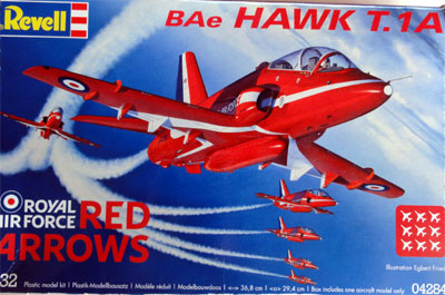
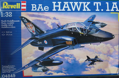
1/32 scale Hawker Siddeley/BAe Hawk jet trainers: REVELL
... continued from page 1 .....
BAe Hawk T.1
Two Revell 1/32 Hawks T.1A models
will be made:
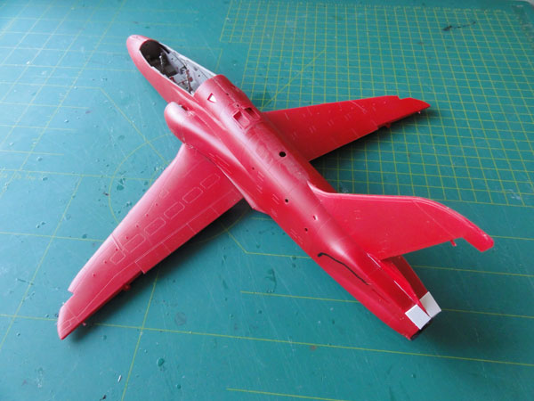
1/ Hawk #04284 "Red Arrows" kit in
terrible Red plastic
2/ Hawk #04849 "RAF" kit in grey
plastic
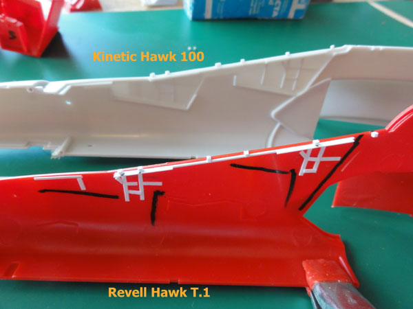
The T.1A had I believe a more flattened rear upper fuselage above the tail pipe whereas the Revell kit shape in that area represents an early production Hawk.
 .
.
The Revell kit instructions are clear.
But first, I started with some minor improvements.
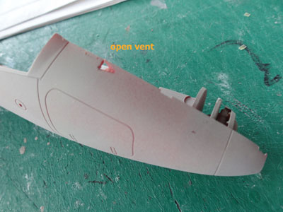
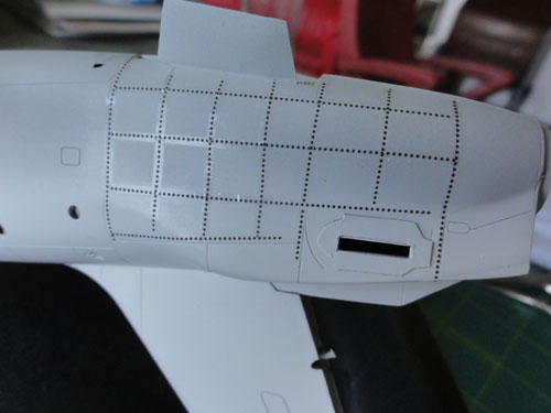
A number of air intake scoops/ vents
are missing:
- one on the nose in front of the
windshield
- and a scoop on each fuselage side
below the base tail fin (is engraved in the kit, but needs to be more prominent).
These were opened up with a scalpel
knife.
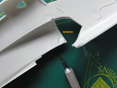
There is an annoying ejector pin mark
inside the left intake section. Remove it, otherwise it will make a nice
installment of the intake tunnel impossible.
Next is an important step....
![]() the
plastic surface of the kit on particularly the wing parts are not smooth
enough. There is a fine grain, but it is not smooth. I heard from a friend
that it will show when trying to apply a gloss paint on the model. It will
simply not work, you do not get a glosh finish.
the
plastic surface of the kit on particularly the wing parts are not smooth
enough. There is a fine grain, but it is not smooth. I heard from a friend
that it will show when trying to apply a gloss paint on the model. It will
simply not work, you do not get a glosh finish.
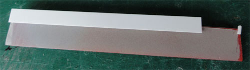
SO IT IS IMPORTANT TO POLISH NOW FIRST THE SURFACES of the main parts, and particularly the wing parts (lower, upper sections). PLEASE DO IT, and BEFORE STARTING ASSEMBLY.
With very fine sandpaper and polish paste like JIF, these parts were polished for about an hour while using plenty of water.
![]()
For the second Hawk model (2)
the same treatment was given to the model.
![]()
The basic kit assembly can start now.
STEP 1
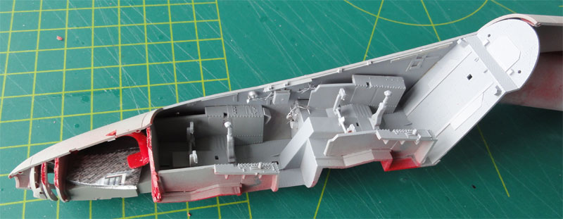
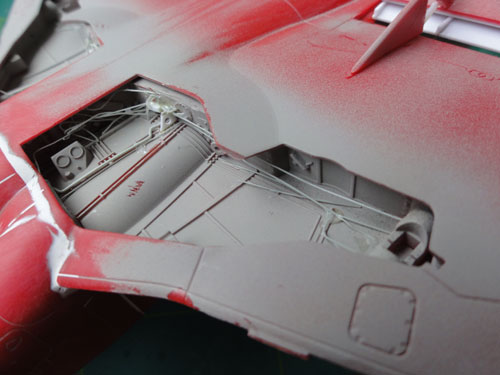
The kit cockpit interior is nice
enough, but may be detailed as desired. The basic panels and tub is OK.
The two pedals #2 are a bit too wide, I removed 2 mm on each side.
Inside the fuselage halves at the
cockpit additional stringer details are seen on a real Hawk. So from card
and rod, add these now. Also, the cockpit edge was made a bit thicker with
plastic strip from EVERGREEN.
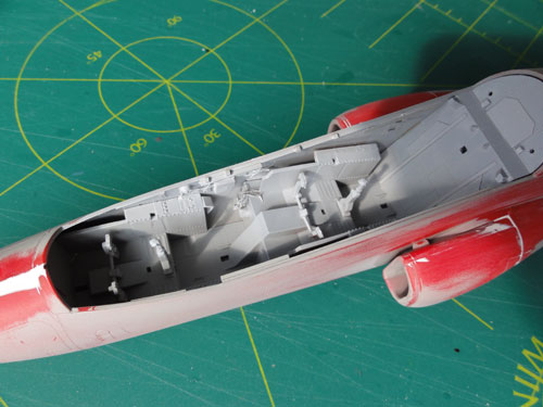
The cockpit interior will be further detailed later on.
STEP 2
The instrument panels are engraved
with additional decals supplied. I think this is OK for this 1/32 Hawk.
I did not bother to drill out all the instruments.
STEP 3
The coaming and rear bulkhead #13
may benefit from some extra detail made from strips and card. This is a
simple thing to do.

Here the bulkhead was given first
a coat of grey to hide the red plastic of the RED ARROWS kit. The white
strip was added.
STEPs 4-5
The Martin Baker Mk.10 seats are
nicely done in the kit. Only couple of seat sides were added made
from thin card as well as some little wiring.
I discovered that the kit seats do
not fit into the tub between the sidepanels due to the too wide lower leg
protection panels. Have I done something wrong?
Probably I will use a resin Mk.10
seat replacement from CMK set #32158 .
The seats were not yet installed
or finished.

STEP 6
The fuselage lights in the kit are
nice, but I added some bits of card inside to prevent a "see through".
The lights themselves will be replaced using Micro Kristal Kleer
to enable spraying.
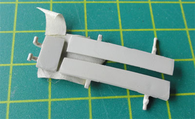
STEPs 7-8 Nose gear well
I found a little difficulty with
fitting the nose gear bay structure. I did not bother to open up the indicated
1 mm hole.
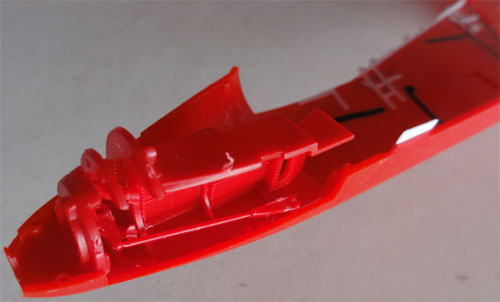
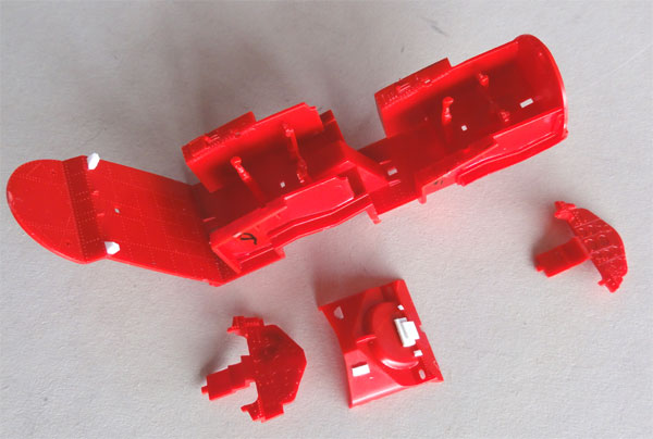
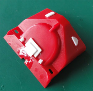
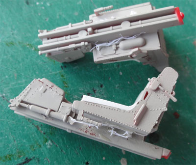
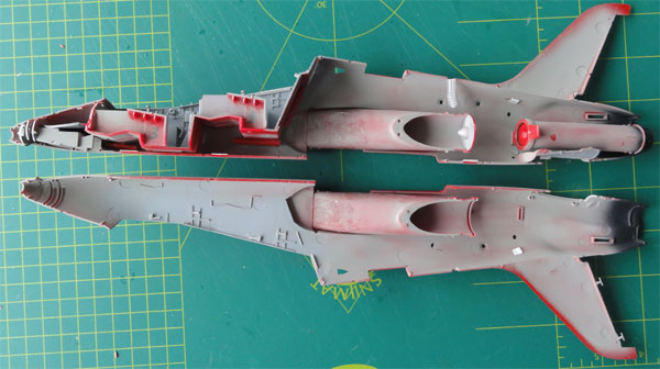
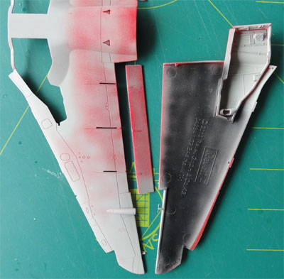
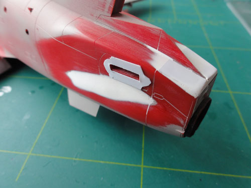
The red plastic I really did not like. I thus gave all the parts of the RED ARROWS kit a base grey coat and black coats inside the wings with the airbrush. (for the grey Hawk T.1 kit this is not required).
STEPs 9-11 and STEP 15
The intake tunnels are nicely provided
in the kit and the exhaust pipe is deep. Well done Revell. The seams are
hardly visible, so a good assembly will suffice here.
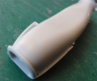
I recommend (as seen in STEP 15)
to combine the tunnel setting inside each fuselage half with fixing
the intake parts #40 and #42. I removed the alignment pins on the intake
parts #41 and #43. Quickly set als the intake and align. The fit is very
good now and no sanding is necessary.
STEPs 12-14
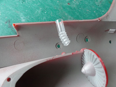
I added a piece of a straw to have
a sort of upper exhaust pipe at the top opening in front of the fin base.
The basic fuselage assembly gave
no problems, but I added a few plastic strips inside to get stronger seams.
Gaps were to be filled along the fuselage joints and upper intake. Do it
now before fitting the wing for easier handling.
STEP 16
Revell provides two types on fin
fillets (#44,45,46,47) , a long and a short one. Both are on the basic
kit sprues. The RED ARROWS Hawk has the short fillet. Check the particular
Hawk you're modelling which fillet type was fitted.
Please note that the upper shape
of the rear end of the kit is too much curved. This a shape error on the
kit. It will be corrected later on with filler and sanding.
![]()
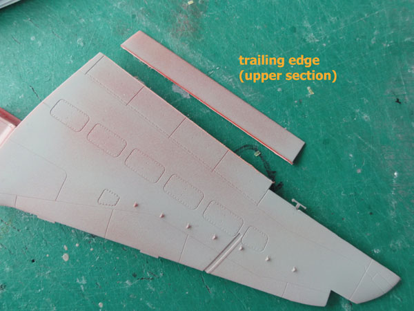
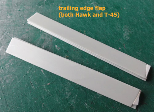
STEPs 17-19 WING
The wing is nicely done by Revell.
However, the trailing edge flaps are moulded with the wing in the UP position.
On a real Hawk, the slotted flaps droop down when the aircraft is parked
on the ground. This means considerable work for the kit when set in a static
ground situation.
So, I removed with a TIGER razor saw
the flap areas.
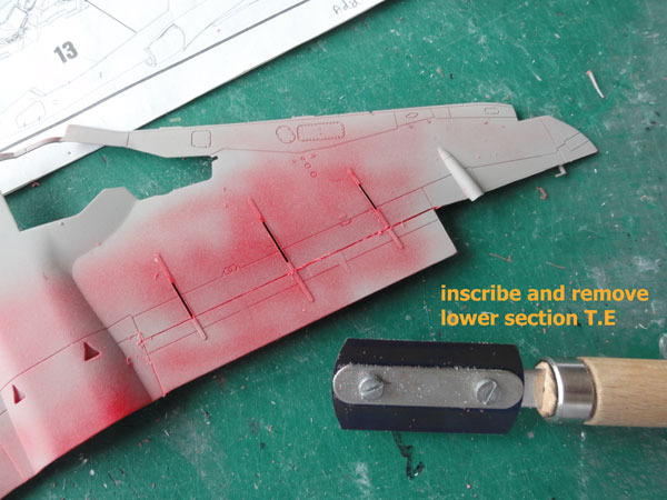
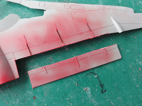
Also, this was done on the upper
wing halves.
The flap has a fixed vane slot covering
about 80% of the flap span (this was done to improve Hawk stall characteristics).
So a separate part was needed for the slot. First, the small gap was closed
at the flap end with card and putty.
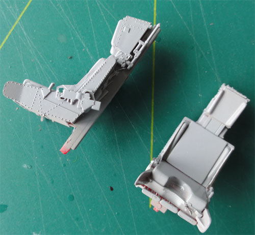
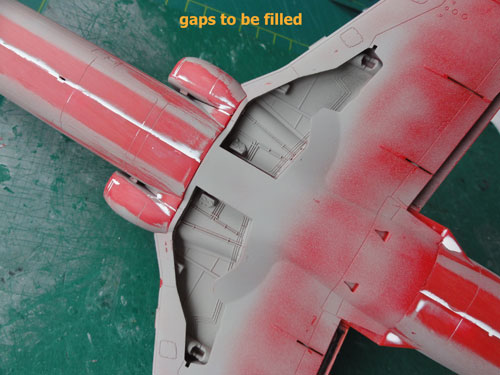
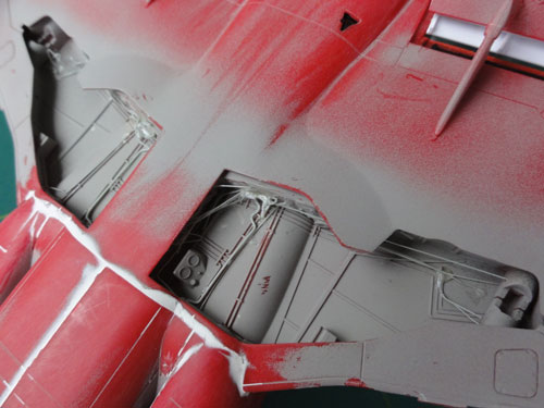
The kit main gear bays are nice, but some additional hydraulic tubing and wiring was added from plastic stretched sprue. Also, some extra rib detail was added from card. On the flap inside, a spar was suggested using pieces of sprue from the kit. This will close the wing rear gaps and make a stronger structure.
STEP 20
The ailerons were assembled but not
yet fitted to the wing.
STEP 21
As the trailing edge flap is drooped,
all hinge parts #81,82,83 need to be cut with a razorsaw and bended. A
rod for the mechanism was added on each flap hinge.
The hinges were NOT yet added onto the wing, first do the basic main wing-fuselage joining as seen in STEP 28. Some gaps were to be filled.
The wing was assembled and joined
with the fuselage.
Filling with putty and sanding after
the putty was dried was done to close all gaps.
Inside the main gear bays, some additional
wiring and hydraulic pipes were added made from stretched sprue. The doors
were obviously not (yet) fitted.
.
As noted before, the T.1A had I believe a more straight rear upper
fuselage above the tail pipe whereas the Revell kit shape in that area
represents an early production Hawk.
So in the kit if you want a T.1A the rear upper fuselage is TOO much curved. Also the bulge of the exhaust area is TOO prominent. The curve can be easily flattened by adding cart, putty and sanding it in shape. The bulge itself was made less prominent simply by adding filler.
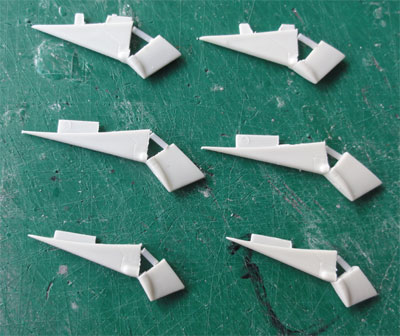
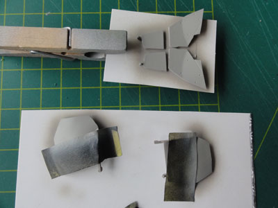
STEP 43 (or 44)
The 2 ventral fins were now also
simply set in place
The result of filling and sanding
is seen here:
Also, an "end-swivelling" plate from
thin card was added at the stabilizer hinge. This is well visible on a
real Hawk. Note also the "longer base fin fillet" for this Hawk T.1 model.
Check the particular Hawk you're modelling which fillet type was fitted.
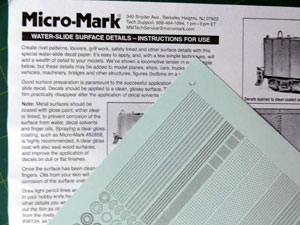
Next, the rear end of the Hawk shows
raised rivets! These are missing on the REVELL kit and very well seen.
Using MICRO MARK rivets decals (with resin raised rivets), several
strips of rivets were added. The work like decals, cut in strips and applied.
 (seen on the grey Hawk kit)
These rivets will show when given
the coat of desired end-paint.
The nose gear doors were separated as the undercarriage would be deployed/extended.
STEPs 23-24
The stabilizers were assembled. Also polish their surfaces!! Otherwise you will never get a smooth gloss paint finish.
STEPs 25, 26
The landing gear parts are fine.
Only some brake wires were added from sprue.
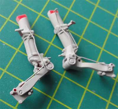
The main gear doors as in the kit were simply used and given a grey base coat.
STEP 28 WING
As noted before, the trailing edge
flaps were cut loose and to be drooped.
From plastic EVERGREEN strip the separate flap guide vane was made, I did not bother to add a winged airfoil profile, plain card was used. The vane resides on the rear flap and below the wing trailing edge, so is hardly seen what the shape is.
Bits of rod were glued between the
vane and the flap to have a gap.
Here all seen with a grey coat of
primer.
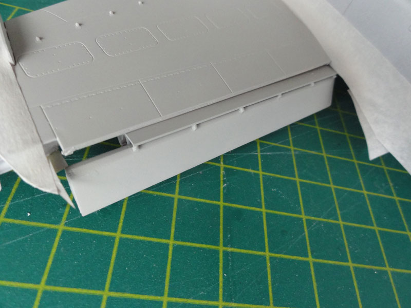
The flap hinge fairings were joined
at this stage on the lower wing and the drooped flap added to help airbrushing
the model..
*(alternatively do this separately).
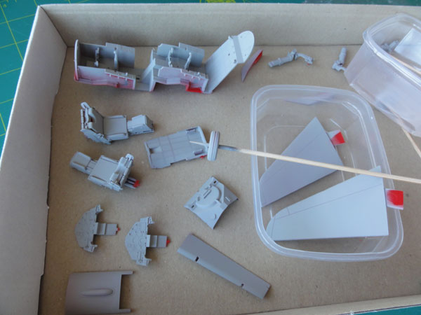
For the second Hawk model (2) the same treatment was given to the model. This results in two 1/32 Hawk T.1 models to be finished.
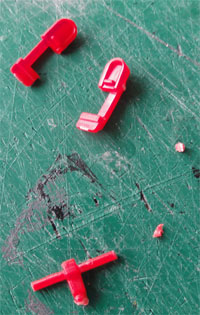
Some parts are seen here
On to next [ Hawk
Page 3.... ]
Back to 1/32 Models.......

(c) Copyright Meindert "designer"/ All rights reserved. Your comments are welcomed by webmaster
Created this page
June 11 , 2013