in 1/32 scale
[ page 2 ]
F-86D (called "Sabre dog") 1/32 scale Kitty Hawk kit
... continued from page 1....
STEP 7
The engine is to be kept separate.
Do not fit yet the cockpit tub of step 2.
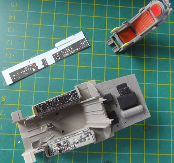
STEP 8
See notes above on the main instrument
panel that was made differently.
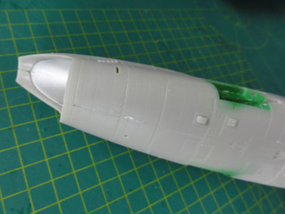
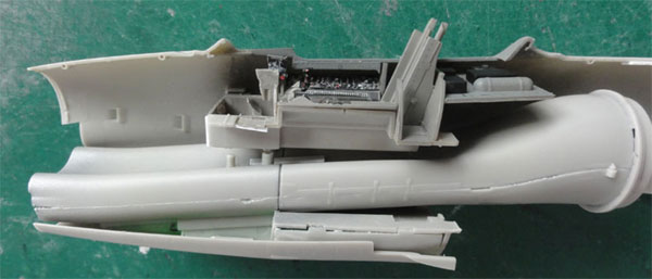
This step particularly deals with fuselage assembly. I took a different approach to glue together the left forward fuselage C27 and left rear fuselage part F4. This to ensure a nice clean fit and to avoid a big step in the seam. (So the he bulkhead parts D6 were not required).
Strips of thick plastic were used
to strengthen the bond. Let dry for an hour on a flat surface and it turned
out that although the fit is pretty good, still some sanding is needed.
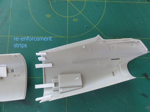
Please note that the right halves
are NOT joined together. They will be mated later on to the left fuselage
to get better alignment.
Inside the fuselage halves, I taped tape to avoid see throughs the very nice slots and intakes that are nicely moulded opened up.
The NACA ducts parts C19 and C21 (shown in step 18) were also set in place here to get a better flush fit. These were usually seen of JASDF and Asian Sabredogs but seldom on USAF aircraft. They fit very well. Please note that there are variations on these ducts between F-86D Sabre Dogs, so check a real photo of the model you want.
Also, the brake recess parts D40 and D41 were set in place, I needed to make them 1 mm shorter in length.
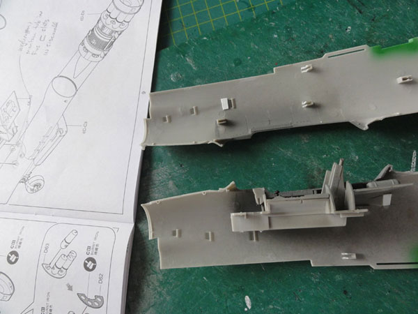
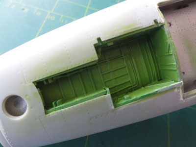
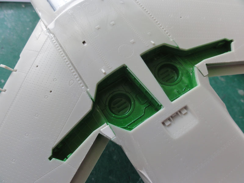
STEP 9
The main gear bays are well detailed.
make sure not to mix up the parts. Interior green is usually the colour.
Some wiring and hydraulic piping will be added later on. Wait with fitting
it further until left and right fuselage halves are joined.
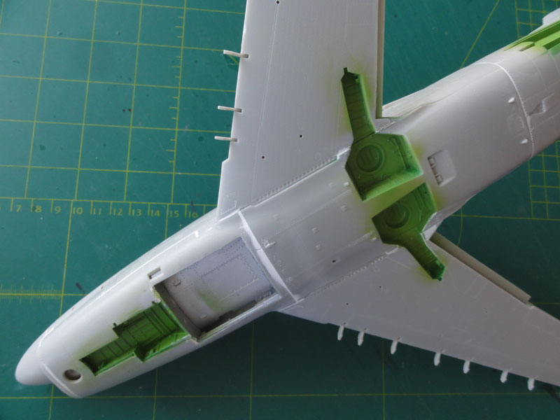
STEP 10
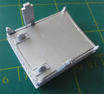
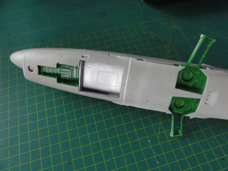
The ventral FFAR rocket tray can
and will be set in "deployed" lower position. Part C28 was used inside
the recess. The rocket tray and bay insides were airbrushed metal and set
aside for later installment. (When you choose a closed tray, ensure it
is blended in during STEP 12 with the fuselage).
STEP 11
There are some parts for the AN/APG-37
weather- and intercept- radar, but the nose would be set closed so this
step was skipped.
STEPs 12 + 13
First, the self made rear exhaust
pipe combined with the part D50+D56 (see step 13) was set into the rear
fuselage. Fit is good. The deep exhaust pipe looks good.
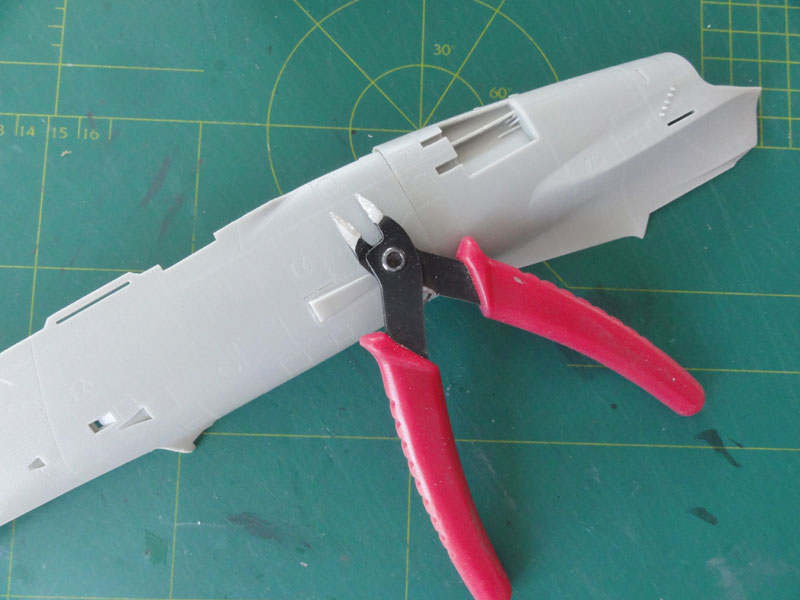
Next I now attached the right rear
fuselage to the left halve. Fit is very good. In order to get some internal
strength, I added a couple of thick sprue bars to avoid compressing and
squeezing the fuselage.
 .
.
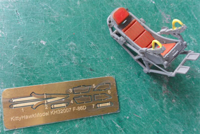
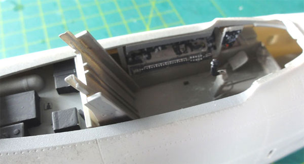
The tub and seat of step 2 were painted
at this point as this is much easier now before installment inside the
fuselage. (Seat is kept loose and seat harness to be added later).
I added pieces of card in front of the steering pedals to avoid see through
(not yet seen here).
The rear cover plate E61 is undeep
but I could not find pictures that suggest otherwise. Simply installed.
The trub and the upper instrument coaming panel C7 will be further detailed
later on.
There are also PE metal seat straps.
After paint was dried, I inserted
the cockpit tub. In order to fit the cockpit tub, I installed it into the
fuselage side "U-shaped" slots. I cut of the lower notches in order to
avoid interference with the lower intake duct. I had to remove about 2
mm from the stubs at the tub to get a good alignment inside the fuselage.
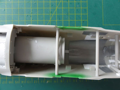
Next came the assembly of the ducts
and lower forward fuselage section as described in step 9.
Also, insert WEIGHT into the nose.
I picked a heavy metal bar and installed it on top of the forward duct
forward of the cockpit. Note also the peice of card set in place at the
forward tub edge to prevent "see through".
The fuselage as a whole was now assembled.
As noted before, the lower fuselage fairing part C17 was joined with ducts and the nose gear bay earlier. The fitting of the central lower fuselage belly with bays and forward lower fuselage was surprisingly easy!
A gap was there between the mid C20
and forward lower section C17 but probably that was my own fault. A strip
of 1 mm was inserted, gaps filled and sanded when dried.
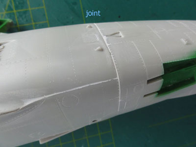
Still, I had some small gaps and step
at the rear joint. But nothing that can not be solved with some putty and
sanding. All in all, not too bad for such a complex kit.
The nose wheel doors and main gear doors were assembled but NOT yet set in place. To be set at a later stage to avoid damage.
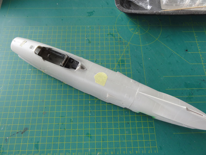
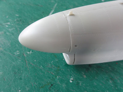
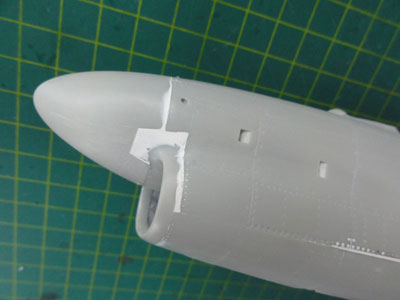
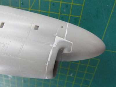
The nose intake ring C12 is fitted (there is a spare one for the F-86K with the gun port). I also fitted the radar nose part E3. Fit is even with the intake duct pretty good but obviously some filler was still needed.
Now, first do a puttying and sanding
when dry onto the main fuselage assembly.
This as handling is easier without
yet the wings installed.
I use usually white car filler from
ALABASTINE.
It turned out that only some small amounts of putty were needed. A very nice engineered model indeed.
 .
. .
.
 .
.
and the rear sections.
![]()
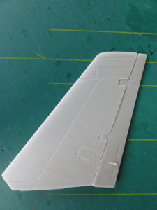
STEP 14
The vertical tail has nice separate
rudder. It was not yet set in place, will be done after wing halves are
fitted.
The stabilizer lower areas nicely
shows the various vortex generators, although they are a bit flat. But
leave as is.
STEPs 15 + 17
The wing halves are nice with separate
flaps, ailerons and slats. On real Sabres these are often drooped down
for a parked aircraft. Obviously, do not yet fit these now. Assemble only
for now the flaps and ailerons parts.
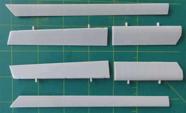
First glue each wing halve upper and lower section. BUT DO NOT GLUE entirely at the aft section near the gear bay. This will make fitting each wing halve onto the fuselage combined with the main gear bays struts (as seen in step 9) easier.
STEP 18
Each wing halve is fitted onto the
fuselage. The fit is remarkably good! Do not press too hard. Let glue flow
in place at the joints. Make sure there is a bit dihedral, the kit is good
here. Leave the wing to dry for a couple of hours.
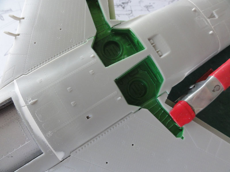
There is a small "ridge" at the joint,
but I believe that is correct. I added a piece of card at the rear
and will put some filler and sand flush later.
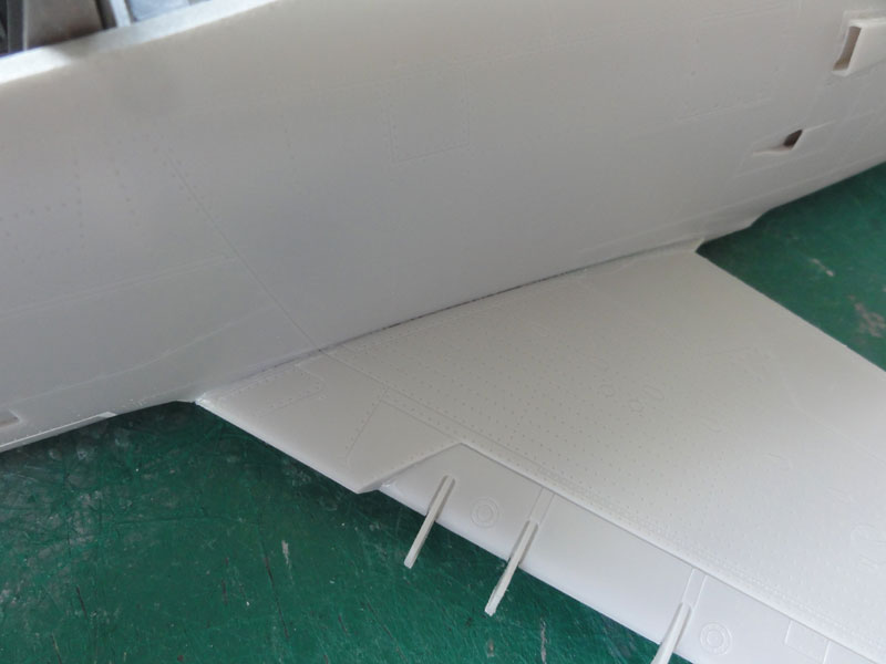
The upper wing-fuselage joint is
very good indeed!
Do not fit yet the stabilizer parts.
Meanwhile proceed with....
Now fit the vertical tail from step 14 onto the upper rear fuselage. Fit is good with some white glue to fill the tiny gaps. Ensure a vertical fit.
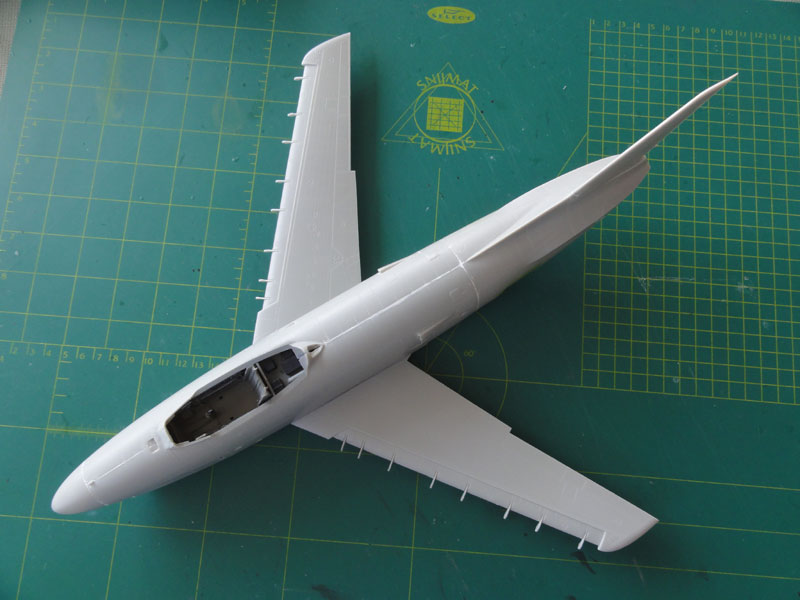
FINAL ASSEMBLY NOT YET
Fitting stabilizers, wing slats and
flaps and stores are not yet done. First some main paint work is done before
adding the undercarriage gear, air brakes and so on.
The model is now ready to receive
the first base grey coat to check for any flaws and seams.
On to next
[ Page 3... ]
Back to 1/32 Models
(c) Copyright "designer"/ All rights reserved. Your comments are welcomed by webmaster
Created August 29, 2015